Description
of
the
PC
Modem
1
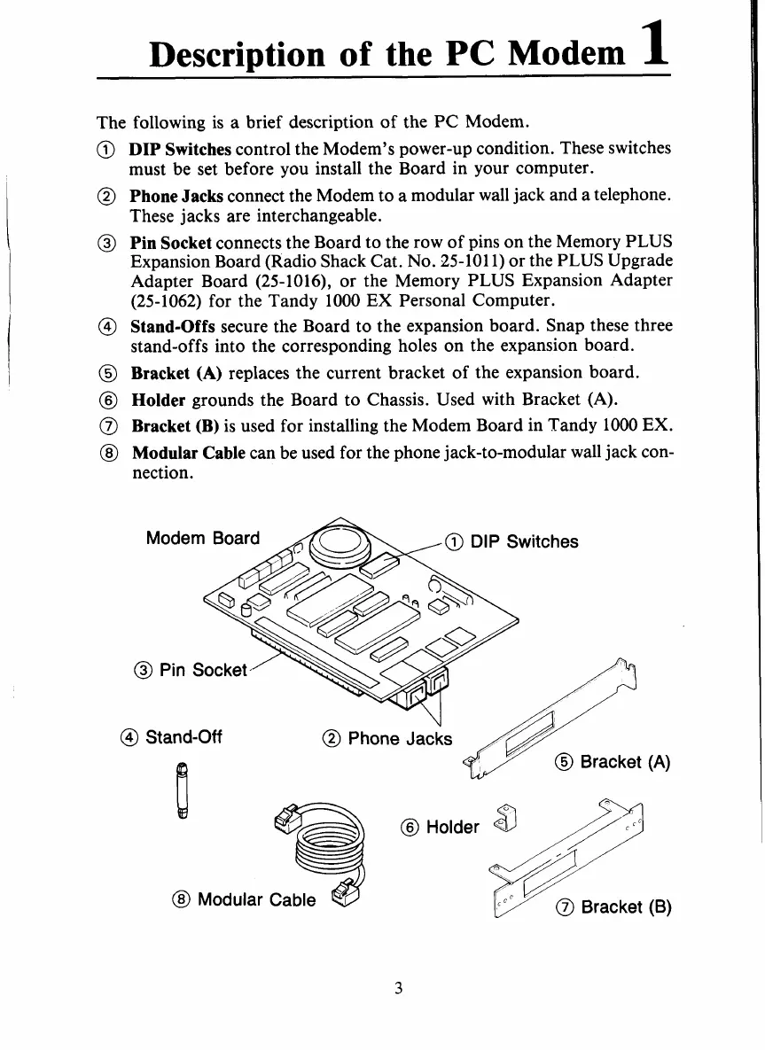
The following is
a
brief description
of
the PC Modem.
@
DIP Switches
control the Modem’s power-up condition. These switches
must be set before you install the Board in your computer.
@
Phone Jacks
connect the Modem to a modular wall jack and a telephone.
These jacks are interchangeable.
@
Pin Socket
connects the Board to the row of pins on the Memory PLUS
Expansion Board (Radio Shack Cat.
No.
25-101
1)
or the PLUS Upgrade
Adapter Board
(25-1016)’
or the Memory PLUS Expansion Adapter
(25-1062)
for the Tandy
1000
EX Personal Computer.
@
Stand-Offs
secure the Board to the expansion board. Snap these three
stand-offs into the corresponding holes on the expansion board.
@
Bracket
(A)
replaces the current bracket
of
the expansion board.
@
Holder
grounds the Board to Chassis. Used with Bracket (A).
@
Bracket (B)
is used for installing the Modem Board in Tandy
1000
EX.
@
Modular Cable
can be used for the phone jack-to-modular wall jack con-
nection.
@
Stand-Off
@
Holder
ccc
@
Bracket
(B)
3
 Loading...


