22
* DISPLAY LEGEND:
CH= Gate closed tE= Self-learning
CL= Gate closing ST= Stop pressed
OP= Gate opening AS= Amperometric protection intervention
AP= Gate open
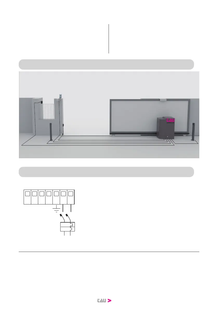
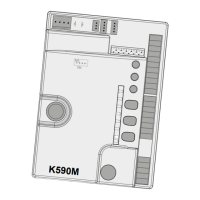
6. ELECTRICAL SYSTEM DIAGRAM
7. ELECTRICAL CONNECTIONS
7.1 Power line connection
13 14 15 16 17 18 19
xx
16 A
230 V AC
N F
The power supply line must have a three-pole
cable of at least 2.5 square meters per pole, it
must be protected by a 16 A magnetothermic
switch and a 30 mA dierential.