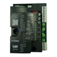
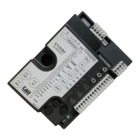
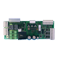
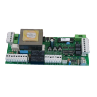
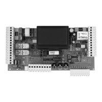
TERMINAL BOARD CONNECTIONS
Terminals Function Description
1 + 2 POWER SUPPLY POWER input 230/115 V AC 50-60 Hz. 1= NEUTRAL 2= PHASE;
3 + 4 FLASHING LIGHT
FLASHING LIGHT output 230/115 V AC, max. 50 W. The signal is already modulated for direct use; fast ashing during
closing, slow during opening. 3= 230/115 V AC, 4= 0 V AC;
7 + 10 OPEN/CLOSE OPEN/CLOSE input (Normally Open contact);
8 + 10 STOP STOP input (Normally Closed contact);
9 + 10 PHOTOCELLS
PHOTOCELLS OR SAFETY DEVICES input; active during closure (Normally Closed contact); the gate will stop during clos-
ing and totally reopen it, (10= Common). If there is more than one safety device, connect all the NC contacts IN SERIES.
11 + 12
24V AC
PHOTOCELLS
24 V AC 10 W output to Photocells, Receivers etc.; connect a up to 3 pair of photocells. 11= 0 V AC, 12= 24 V AC;
13 + 14 AERIAL 433,92 MHz built-in RX aerial input; 13= EARTH, 14= SIGNAL;
M2 LIMIT SWITCH
Quick coupling for LIMIT SWITCH connection (Normally Closed contacts).
ORANGE= Closing Limit Switch (CLS), RED= Opening LimitSwitch (OLS), GREY= Common (COM);
FS1 + FS2 CAPACITOR CAPACITOR Terminals for motor start-up;
M3 MOTOR
Quick coupling for 230 V AC single-phase MOTOR connection. BLUE= common (M-COM);
BROWN= closing (M-CL); BLACK= opening (M-OP).
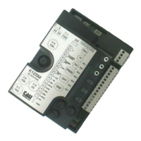
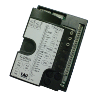
LOGIC ADJUSTMENTS
TRIMMER
FR.
Motor torque adjustment. Turning the trimmer clockwise (+) the torque will be increased; Turning the trimmer counterclockwise (-) the
torque will be decreased.
Note: The trimmer is set to provide sufcient thrust to work the gate within the limits established by current standards (EN 12453).
SENS.
Obstacle detection setting. Turning the trimmer clockwise (+) the sensitivity will be increased; Turning the trimmer counterclockwise (-)
the sensitivity will be decreased.
Note: Before setting the obstacle detection, let the gate operator perform a complete opening and closing cycle.
T.C.A.
Automatic closing time adjustment. Turning the trimmer clockwise (+) time will be increased; Turning the trimmer counterclockwise (-) the
time will be decreased.
Note: The time values can be set between 1 and 120 seconds.
Dip switch
1
AUTOMATIC
CLOSING
On automatic closing enabled.
Off automatic closing disabled.
2 2 / 4 STROKE
On (with Automatic closing enabled) Two-Stroke operation mode OPEN-CLOSE, OPEN-CLOSE, etc.
Off
(with Automatic closing enabled) Four-Stroke operation mode OPEN-STOP-CLOSE-STOP, OPEN-STOP-CLOSE-STOP,
etc.
3 SOFT-STOP
On Soft-Stop Learning procedure activated (see next chapter);
Off No Soft-Stop, Working time will be set to 240”.
4
OPENING
DIRECTION
On Left-hand leaf opening mode;
Off Right-hand leaf opening mode;
SOFT-STOP SETTING
With the sliding gate open, set DIP 3 in ON. DL1 LED will start ashing fast.
Close the AP/CH contact or press the OP/CL pushbutton: the operator will start closing the gate until the Closing Limit Switch (CLS) is reached.
Once the Closing Limit Switch (CLS) is reached, the operator will reverse the cycle and start opening the gate:
1_ Close the AP/CH contact or press the OP/CL pushbutton when the desired start point of the Soft-stop is reached;
2_ Once the Opening Limit Switch (OLS) is reached, the gate will stop. DL1 LED will turn ON (start point set);
3_ If the STOP contact is opened the procedure is interrupted, the gate will stop and DL1 LED will ash to advise that the procedure is still active
(Close the AP/CH contact or press the OP/CL pushbutton to restart the procedure from the beginning).
Note: SOFT-STOP settings apply both to opening and closing.
ATTENTION: to modify the SOFT-STOP settings it is necessary to repeat the whole procedure.
K100M FEATURES
DL1 LED
Other than indicating the programming of a transmitter is going on, DL1 LED advises error messages as follows:
Steady light: Normal operation;
Fast ashing: Soft-Stop learning procedure activated;
Slow ashing: Automatic 50 / 60 HZ Frequency Detection Error;
Contact Technical Service;
6 ashes: 5 x failed attempts to close due to the presence of obstacles;
Make sure the gate slides smoothly and without obstacles in both directions;
7 ashes: No learning procedure executed;
Perform learning procedure.
8 ashes: No motor signal;
Check wiring - Make sure the motor can rotate freely;
Multiple errors are indicated by a 2” pause between error messages. Messages will be shown until a complete opening/closing cycle is performed.
In the event of 3 consecutive activations (during the same closing manoeuvre) of the amperometric control (obstacle detection), the control unit opens
completely on the next manoeuvre. To reset, the automation must complete a manoeuvre (opening and then closing); otherwise the end stop search pro-
cess will be repeated after each activation of the amperometric control.
In the event of activation (during the opening manoeuvre) of the amperometric control (obstacle detection), the control unit closes approx. 20 cm. stopping
the automation. On the next manoeuvre the control unit closes completely.
WARNING: the control panel logics may interpret mechanical friction as an obstacle.
ADVANCED FUNCTIONS
Clock function: a timer can be connected to the open-close pushbutton in order to keep the gate open at certain times during the day, after which it reverts
to automatic closing.
Note: The gate remains open as long as the OP/CL input continues to be activated.
433.92 MHz BUILT-IN RADIO RECEIVER
The built-in radio receiver can store up to 30 different codes from Rolling Code transmitters (BUG2R, BUG4R, K-SLIM-RP, T-4RP).
The radio channel directly commands the control board for opening the automatic device.
LEARNING PROCEDURE FOR TRANSMITTERS
RADIO = Radio channel
OP/CL = OPEN/CLOSE
RESET= Radio memory reset
1_ press and release the RADIO button on the control unit;
2_ DL1 LED turns OFF to indicate that the programming mode has been activated (if no code is entered within 10 seconds, the control unit will exit the
programming mode);
3_ press and release the transmitter button;
4_ DL1 LED turns ON again to indicate that the new code is stored (if this does not happen, wait 10 seconds and start again from point 1);
5_ to store other transmitters, repeat the procedure from point 1 up to a maximum of 30 transmitters;
6_ to exit the programming mode without storing a code, press and release RADIO button.
Note: When the maximum number of transmitter (30) is reached, the DL1 LED will start ashing fast for about 3”, without performing memo-
risation.
REMOTE PROGRAMMING THROUGH T-4RP and K-SLIM-RP
It is possible to program the new version (V 4.X) of transmitters T-4RP and K-SLIM-RP without actually pressing RADIO button on the control unit.
An already programmed transmitter is capable to activate the programming mode and thus allowing new transmitters to be stored in the receiver memory.
The new transmitters must be prepared using the TAUPROG handheld programmer. Please refer to the transmitter’s instruction manuals.
ERASING ALL PROGRAMMED TRANSMITTERS
1_ press and hold the RADIO button on the control unit for approx. 3” to start the erasing procedure;
2_ DL1 LED ashes slowly to indicate that the erasing procedure has been activated;
3_ again, press and hold the RADIO button on the control unit for approx. 3”;
4_ DL1 LED turns off for approx. 3”, then turns ON To indicate that all stored codes have been cancelled;
5_ to exit the erasing mode, press and release RADIO button.
RADIO MEMORY HARD RESET:
- press without releasing keys RESET and OP/CL till LED DL1 starts ashing quickly. At this point release the keys and press them again till the LED
go off and on again, conrming the operation is complete.
TROUBLESHOOTING GUIDE
Operator does not run
a- Check 230/115 V power supply with a voltmeter;
b- Check that all 4 green LEDs (Normally Closed contacts, DL3, DL4, DL5 and DL6) are ON, and that all two red LEDs (Normally Open contacts,
DL1 and DL2) are OFF;
c- Check that the red DL1 LED is ON;
d- Check that the fuses are intact with a voltmeter.
The radio control has little range
a- Check that the ground and the aerial signal connections have not been inverted;
b- Do not make joints to increase the length of the aerial wire;
c- Do not install the aerial in a low position or behind walls or pillars;
d- Check the state of the transmitter’s batteries.
The gate opens the wrong way
a_ Invert the position of DIP 4 (after having turned off the power to the control unit).
 Loading...