4-10
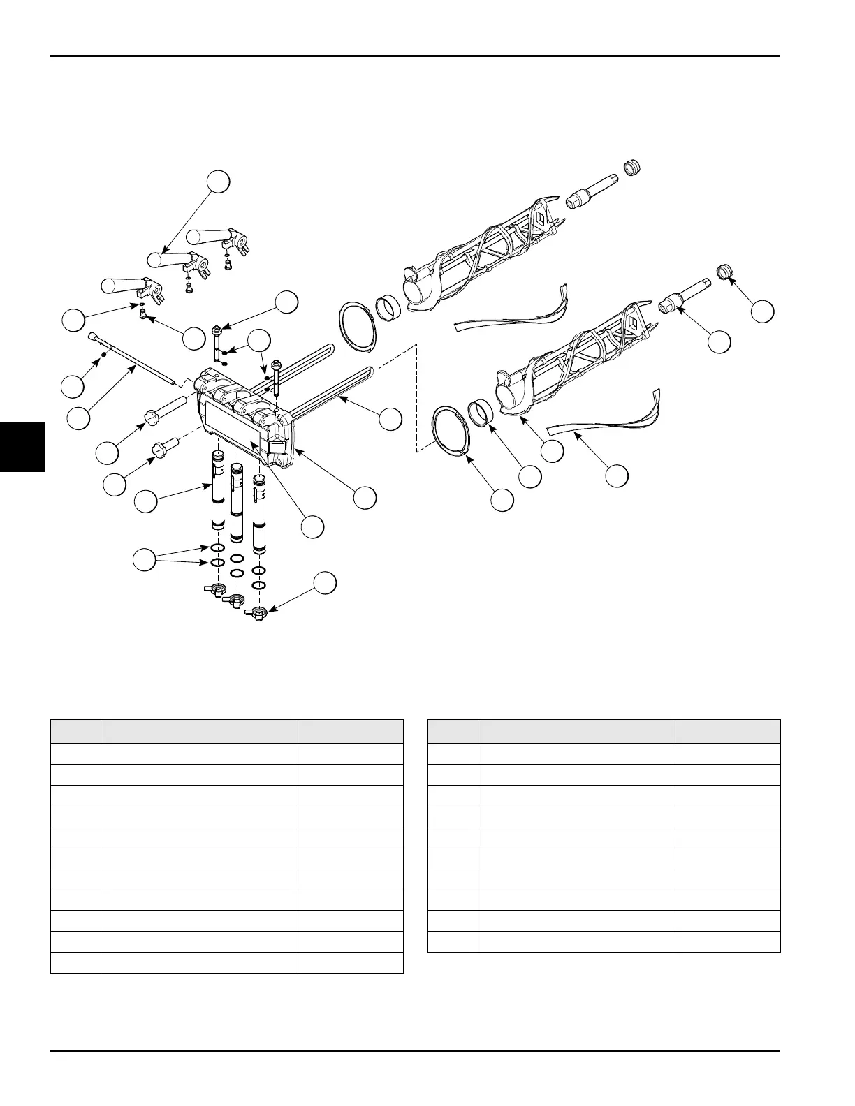
OPERATOR PARTS IDENTIFICATION
Models 750, 751, 754, 774, 791, and 794
Operator Parts Identification
4
Model 791 Three-Spout Door and Beater Assembly
Figure 4-10
14
2
13
8
4
18
9
10
15
6
16
17
10a
7
11
5
12
3
1a
1b
1
Item Description Part No.
1 Handle A.-Draw *White X81010-SP
1a O-ring 1/4OD x .070W 015872
1b Screw-Adjustment 056332
2 Plug-Prime 028805
3 Rod A.-Pivot X20683
4 Nut-Stud *Long 034382
5 Nut-Stud *Short 034383
6 Valve A.-Draw X69539
7 O-ring-7/8 OD x .103W-SIL 083693
8 Cap-Design 014218
9 Decal-Door-3 Spout 021521
Item Description Part No.
10 Door A.-3 Spout X51532-12
10a Baffle A.-Long 4 IN X50882
11 O-ring-Prime Plug 016137
12 O-ring 5/16OD x .070W 016272
13 Gasket-Door HT 4" 048926
14 Bearing-Front 050216
15 Beater A.- Helicore X31761
16 Blade- Scraper 035174
17 Shaft-Beater 032564
18 Seal-Drive Shaft 032560

 Loading...