Table of Contents
028754-M i
Section 1: To the Installer
Installer Safety ...................................................................................................1-1
Site Preparation .................................................................................................1-1
Air-Cooled Machines..........................................................................................1-1
Water Connections.............................................................................................1-2
Electrical Connections........................................................................................1-2
Beater Rotation..................................................................................................1-3
Refrigerant .........................................................................................................1-3
Section 2: To the Operator
Compressor Warranty Disclaimer ......................................................................2-2
Section 3: Safety
Section 4: Operator Parts Identification
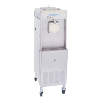
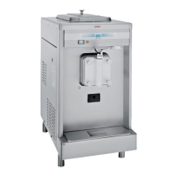
Model 750 ..........................................................................................................4-1
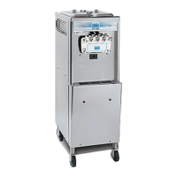
Model 751 ..........................................................................................................4-2
Model 754 ..........................................................................................................4-3
Model 774 ..........................................................................................................4-4
Model 774 Topping Pump (053794-) .................................................................4-5
Model 791 ..........................................................................................................4-6
Model 794 ..........................................................................................................4-7
Models 750 and 751 Single-Spout Door and Beater Assembly.........................4-8
Models 754, 774 and 794 Three-Spout Door and Beater Assembly..................4-9
Model 791 Three-Spout Door and Beater Assembly .......................................4-10
Accessories......................................................................................................4-11
Section 5: User Interface
750/751..............................................................................................................5-1
754/774/791/794................................................................................................5-1
Symbol Definitions .............................................................................................5-2
Power Switch .....................................................................................................5-2
MIX LOW Indicator Light....................................................................................5-2

 Loading...