MPPT charge controller User Manual
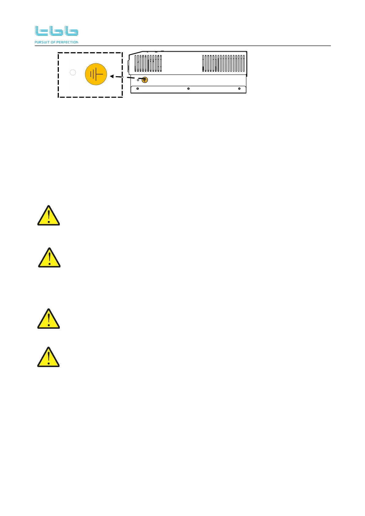
Figure 3-8 Grounding terminal
Using proper gauges of wires for grounding, recommending 16mm²~35mm².
Please connect the SP grounding terminal to the system grounding bar, refer to Figure 3-6 of
chapter 3.5.1.
Please connect the frame of PV to the system grounding bar, refer to Figure 3-6 of chapter
3.5.1
Please connect the battery frame to the system grounding bar, refer to Figure 3-6 of chapter
3.5.1.
Do not connect either the PV negative or the Battery negative to ground. They must be
connected to corresponding terminal marked at connection compartment. Negative
ground might cause equipment damage which is out of warranty.
Do not connect the PV negative and battery negative terminal together at any place of
the system. They must be connected to corresponding terminal marked at connection
compartment of SP. Wrong connection might cause equipment damage which is out of
warranty.
3.7 PV Array Connection
The Voc (open circuit voltage) and Isc (short circuit current) of PV array must never
exceed allowance. Please also consider the local temperature condition which might
result in the increase of PV array Voc/Isc. Refer to chapter 3.5.2.
Whenever a PV array is exposed to light, a shock hazard exists at the output of wires or
terminals. To reduce the risk, cover the array with a dark material before making the
connection.
Choose the right cable size (refer to Table4-4) and follow polarity guide marked on the panel.
Please use the shortest cable to connect and ensure the secure connection.
Please connect PV array to MPPT charge controller. Positive terminal “+” of PV array to “PV +”
of the MPPT charge controller terminal connection. Negative terminal “-” of PV array to “PV -”
of the MPPT charge controller terminal connection .
Wiring need to be protected against any potential physical damage.
Pull through the DC cables through the holes at front panel, clamping the cable terminal on
cable.
Secure the battery cable on BAT+ and BAT- terminals respectively making sure it is tightly
 Loading...