Energier Apollo User Manual
15
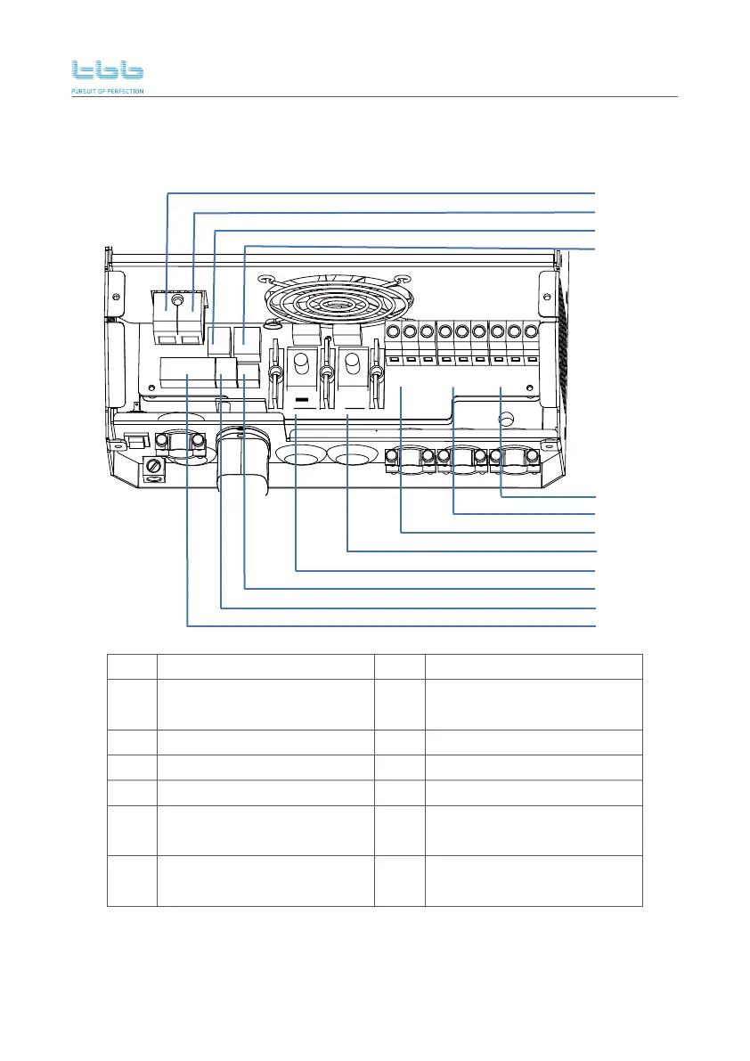
3.2.2 Wiring area view after remove upper service panel
No. Description
PV- terminal
Description
AC output 1 terminal
(L,PE,N from left to right)
BTS terminal
PV+ terminal
13
15
14
RS485 terminal
AC output 2 terminal
(N,PE,L from left to right)
AC input terminal
(N,PE,L from left to right)
17
18
16
No.
19
21
20
23
24
22
Battery+ terminal
VS terminal(VS-,VS+ from left to right)
Battery- terminal
Dry input
Dry output contact
13
14
15
16
17
18
19
20
21
22
23
24
PV+
+
PV-
AC OUTPUT1
L PE N LPEN LPEN
AC OUTPUT2AC INPUT
NO1 COM COMNC1 NC2 DRY IN VS- VS+NO2
CAN
RS485
BTS
 Loading...