Energier Apollo User Manual
23
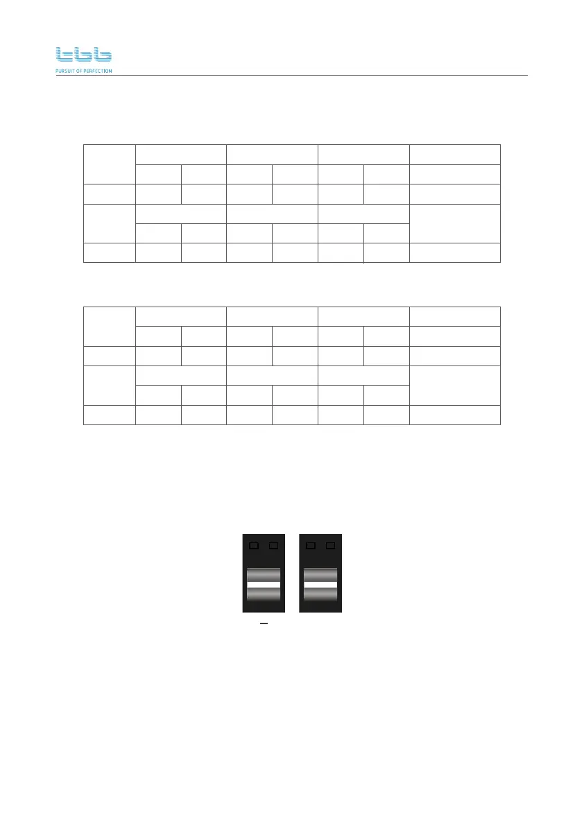
The PV terminals can be found at the bottom of the enclosure, see section 3.2 wiring area description.
Do not invert positive terminal “PV +” and minus terminal “PV -” when connecting the PV cables.
Procedure
For CH2.0M (Max PV open circuit voltage (Voc) 100V):
The PV positive cable should be connected to the “PV +” port. And the PV minus cable should be
connected to the “PV -” port. The PV cable must be protected by a fuse or magnetic circuit breaker,
and cable cross section must be sized accordingly.
Battery
Voltage
36 cells Voc<23V 54 cells Voc<34V
24V
Battery
Voltage
24V
48 cells Voc<31V
60 cells Voc<38V
4 2
max best max best max best
3
72 cells Voc<46V
2 2
96 cells Voc<62V
2
2 2
max best max best max best
2 1 1 1
80V<Thin-film
module Voc<100V
1
For CH 2.0S, CH3.0S, CH4.0S (Max PV Open circuit voltage (Voc) 150V):
Battery
Voltage
36 cells Voc<23V 54 cells Voc<34V
48V
Battery
Voltage
48V
48 cells Voc<31V
60 cells Voc<38V
6 4
max best max best max best
4
72 cells Voc<46V
3 4
96 cells Voc<62V
3
3 2
max best max best max best
3 2 2 2
80V<Thin-film
module Voc<100V
1
PV
+
 Loading...