__________________________________________________________________________________________________________________________________________________________________________________________________
TC Electronic A/S Finalizer Service manual page 10
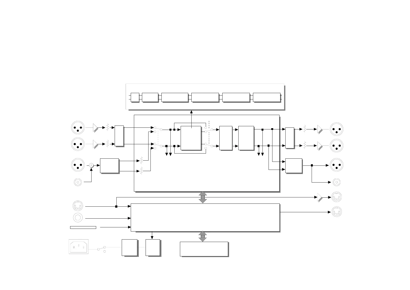
Block Diagram:
The block diagram in figure 7 gives a quick view of the signal flow in the Finalizer.
As the block diagram shows the input and output sections will always be active, even in Bypass mode.
The AES/EBU and the SPDIF inputs are connected internally. Therefore, do not connect cables to both AES/EBU and the SPDIF inputs at the same time.
Signals are present on all outputs, all of the time. To make dithering circuit work, the system must know whether the analog or AES/EBU or SPDIF output is main output.
EXPANDER COMPRESSOR LIMITERINSERTEQ NORMALIZER
SPDIF
AES/EBU
MIDI IN
POWER SWITCH
AT BACK PANEL
OFF
ON
PEDAL IN
PCMCIA
slot
AC
POWER
MIDI OUT
MIDI THRU
ANALOG
INPUTS
[balanced]
L
L
DIG.
RECEIVER
DIG.
TRANS-
MITTER
R
R
DIGITAL
INPUTS
CON/PRO
LEVELS
INPUT
GAIN
OUTPUT
GAIN
BUFFER
BYPASS
DIGITAL
INPUT
GAIN
CON/PRO
LEVELS
DIGITAL
OUTPUTS
ANALOG
OUTPUTS
[balanced]
A/D
D/A
ENGINE
ENGINE
DITHERFADE
MICRO PROCESSOR
FINALIZER
FRONT
POWER
SUPPLY
STAND
BY
SPDIF
Output PPM
sense
Input PPM
sense
AES/EBU
DIGITAL SIGNAL PROCESSOR & DARC
INPUT
SELECTOR