__________________________________________________________________________________________________________________________________________________________________________________________________
TC Electronic A/S Finalizer Service manual page 20
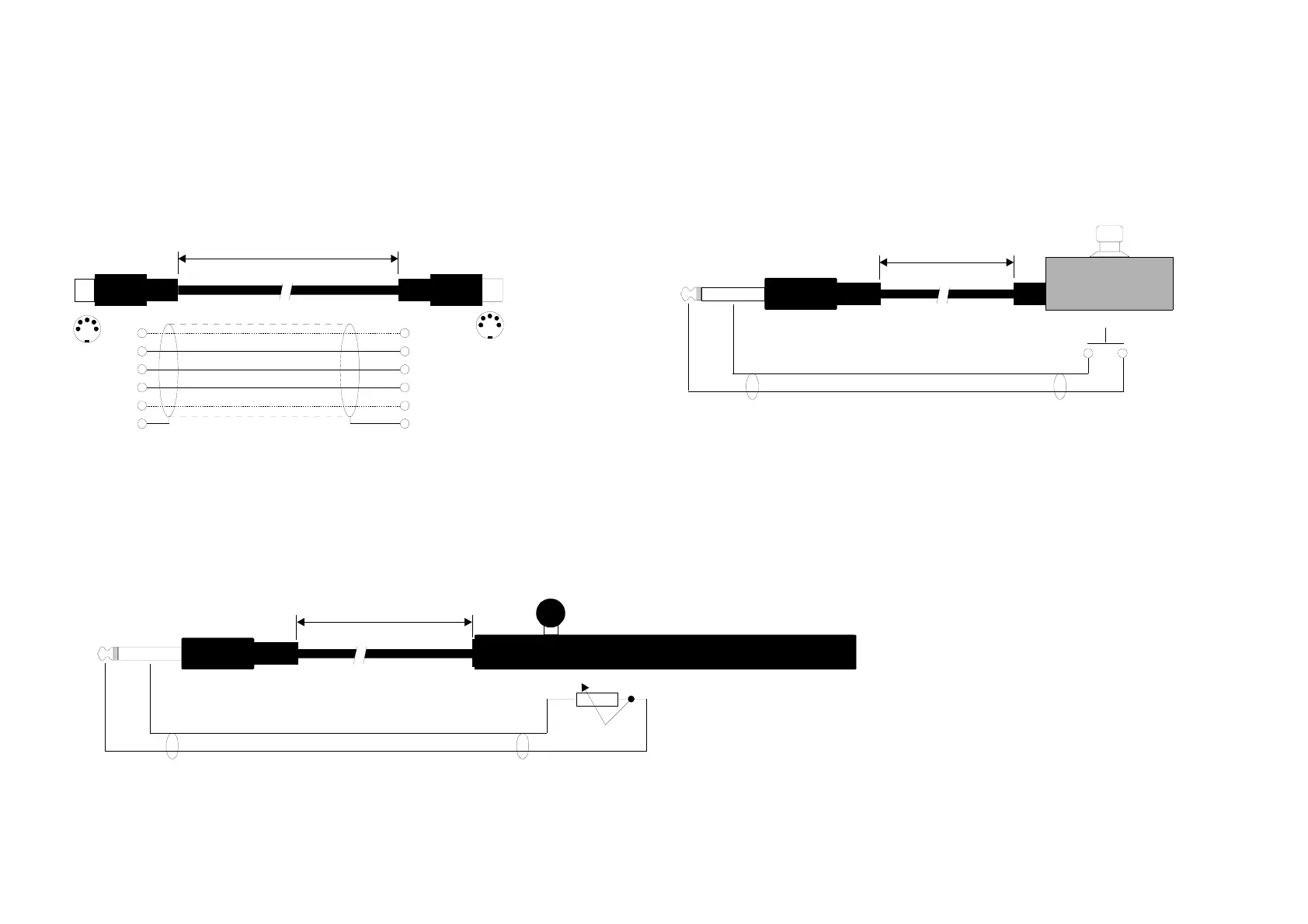
Cable Specifications:
DIN CONNECTOR
JACK PLUG
JACK PLUG
PEDAL SWITCH
or similar
MASTER FADER or similar
MIDI CABLE
PEDAL CABLE
FADER CABLE
DIN CONNECTOR
Note: Pin 1 and 3 at the Finalizer are reserved for optional RS485 interface
Therefore, use only 3-wires if the Finalizer is connected to other equipment that use these pins
max. 15m
max. 100m
max. 100m
5 POLE - MALE
45 degrees
MONO - MALE
Ø 6.35mm, 1/4“
MONO - MALE
Ø 6.35mm, 1/4“
5 POLE - MALE
45 degrees
SHIELDED CABLE ( 3 or 5 wires + shield )
1 wire + shield
1 wire + shield
11
see note
see note
44
2
shield/ground
shield/ground
2
5
Tip
Tip
Switch must be
momentary type
50k ohm = min level
0 ohm = max level
50k lin
5
3
CC
3