__________________________________________________________________________________________________________________________________________________________________________________________________
TC Electronic A/S Finalizer Service manual page 8
Exchange of Power Supply Module
1. Turn Off Power and Disconnect Power Cord.
2. Loosen 5 screws, see fig. 1, and remove the top cover.
3. Disconnect the front connector J2, see fig. 2.
4. Loosen the front section by removing two small
screws at each side panel,
see fig. 6.
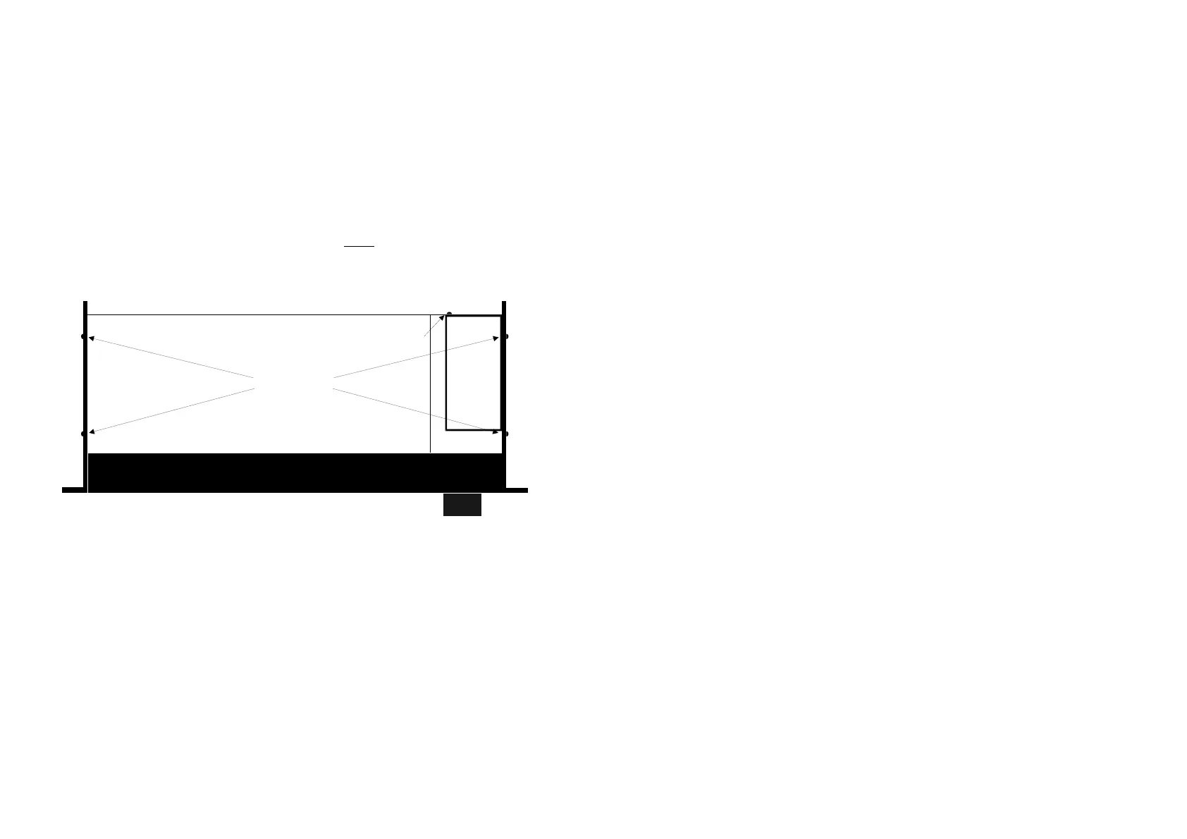
Power
Supply
Top view
4 screws
1 screw
Fig. 6: Screws at side panels.
5 Press out the side panels a little and push gently out the front section.
6 Desolder all seven power supply wires from the main board.
7. Remove the power supply by removing one screw at the back panel, just below
the mains plug, see fig. 6.
8. Mount the new power supply with the screw at the back panel.
9. Solder the seven wires to the main board. Make sure they are correctly placed.
TAKE CARE: The wire ends must not touch the bottom panel!
10. Remount the front section with two screws in each side panel.
Make sure the edge of the bottom panel is pressed into the front profile.
11. Connect the front connector J2.
12 Mount the top lid with five screws.
13. Connect power cord and turn on power.
If the unit has a malfunction; turn off power and check the following:
Is the front connector mounted correctly?
Are the power supply wires correctly placed?
Do the wire ends short circuit to the bottom panel?