__________________________________________________________________________________________________________________________________________________________________________________________________
TC Electronic A/S Finalizer Service manual page 6
Disassembly Procedure for Main Board
1. Turn Off Power and Disconnect Power Cord.
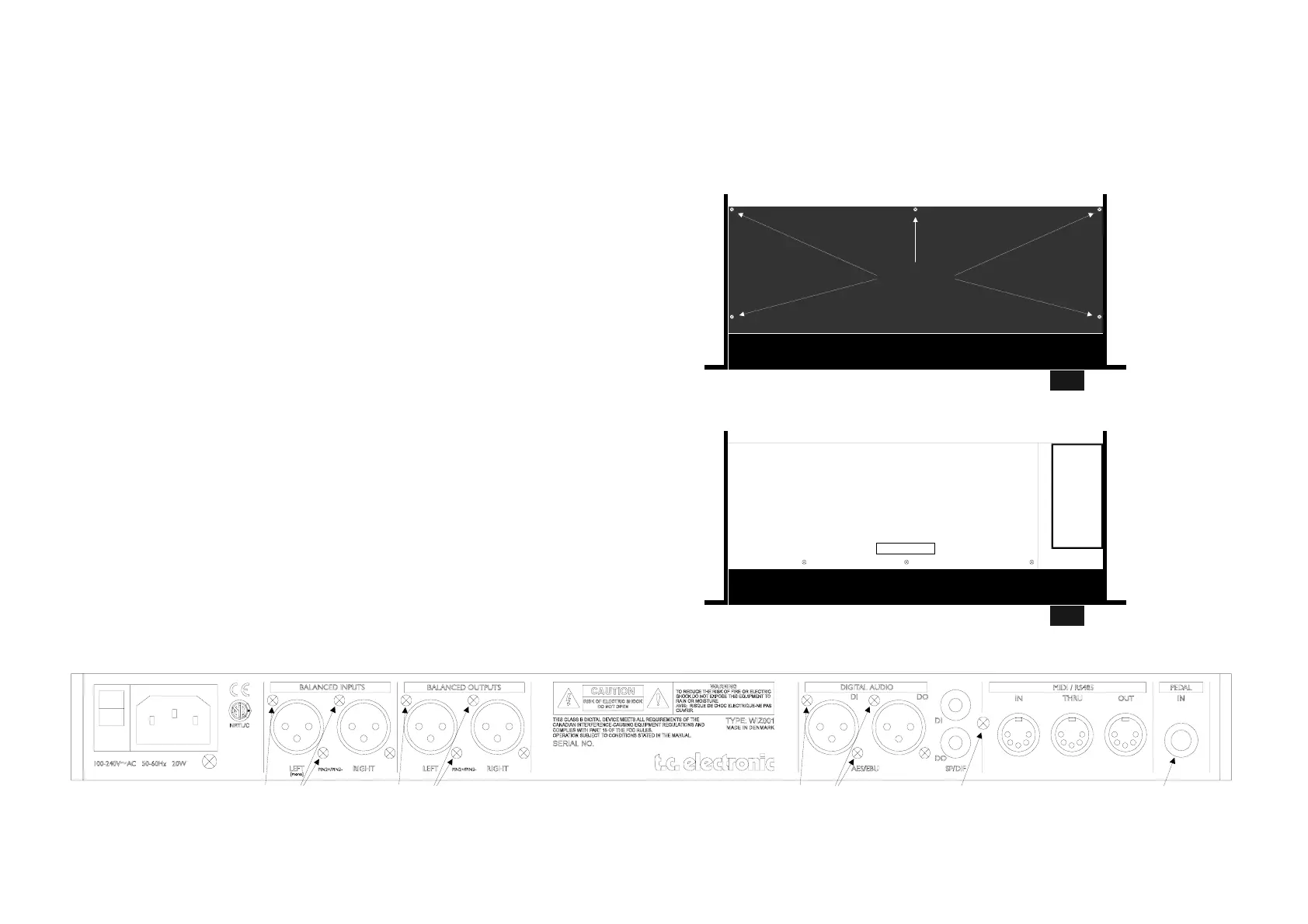
2. Loosen 5 screws, see fig. 1, and remove the top cover.
3. Disconnect front connection, J2, see fig. 2.
4. Remove screws at MT7, MT8, MT2 on the main board, see fig. 2.
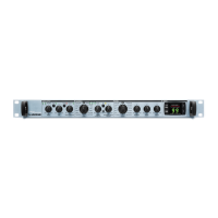
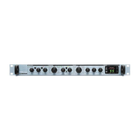
5. Remove screws at the XLR connectors on the back panel, see fig. 3.
6. Remove screw at SPDIF in/out connector, see fig. 3.
7. Remove jack nut at PEDAL IN, see fig. 3.
8. Push the main board into the front profile a little to free the connectors
from the back panel, then lift out the board.
9. Desolder the seven wires from power supply.
Fig. 1: Screws at top lid
5 screws
Top view
Fig. 2: Screws and front connector at main board
MT7 MT8
J2
main board
Power
Supply
MT2
Top view
Fig. 3: Screws at back panel.
LISTED
5D83
PROFESSIONAL
AUDIO EQUIPMENT
MIDI / RS485
1 screw3 screws 3 screws 3 screws Jack nut