__________________________________________________________________________________________________________________________________________________________________________________________________
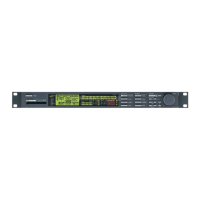
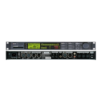
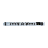
TC Electronic A/S Finalizer Service manual page 14
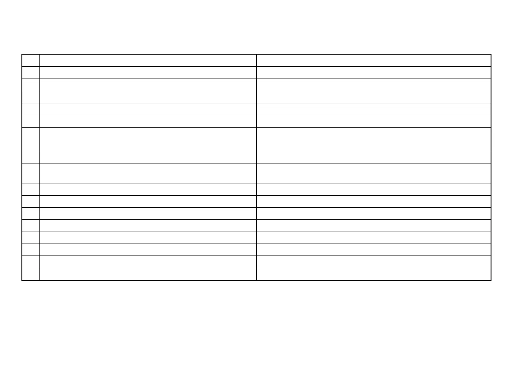
Power On Sequence, continued:
No Event Trouble shooting
7a TP16, DA_DATA starts up IC23
7b TP17, AD_DATA starts up IC18
7c TP26 goes to -3V LD5, IC12 + soldering
7d TP27 goes to +3V LD4, IC12 + soldering
8 TP6, Reset signal goes high. Battery connections, IC30
9 MPU, IC29 checks Checksum in Flash
If OK LD1, LD2, LD3 blink once. If not OK, the LED's stays on. Reload Boot Sector or
replace the Flash, IC35 .
10 MPU checks if TAP button is pressed If pressed; Boot menu appears. Check D11 if no picture.
11 MPU tests SRAM If not OK; message appears: "RAM is corrupted, Settings cleared" . Check IC34, IC30 or
battery.
12 MPU checks header in application software. If not OK; Boot menu appears. Reload application software
13 MPU checks if any BYPASS button is pressed If pressed; Reset menu appears.
14 MPU tests Preset information in SRAM If not OK; message appears: "Preset Error". Check IC34, IC30 or battery.
15 MPU, IC29 pin 107 goes high, (DSP RESET*) IC29 + soldering, see sequence picture in schematics for main board
16a MPU tests DSP If not OK; message appears: "DSP not OK"
16b TP11, ASIC clock starts up, 80MHz IC10 + soldering
17 Picture with user information and software version appears on the display. Front connection, display,
18 RECALL picture appears on the display. Application software,