32
frame paGe
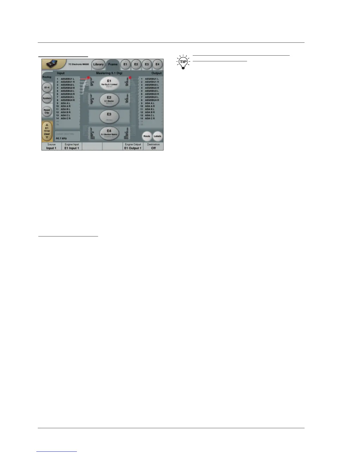
Frame - Routing
Introduction
The Routing page is the patch-bay of the System 6000
Mainframe. All routings of physical Inputs/Outputs as well
as internal routing between the Engines are setup here.
The understanding of this page is therefore essential to
operating the System 6000.
To access the Routing Page:
3UHVVFrame (upper tab)
3UHVVRouting (side tab)
3UHVVRoute to enable routing facilities
This is the page where you:
+DYHWKHRYHUDOOYLHZRIDOO,2¶V
5RXWHSK\VLFDO,QSXWVWR(QJLQH,QSXWV
5RXWH(QJLQH2XWSXWVWRSK\VLFDO2XWSXWV
$FFHVV,QSXWDQG2XWSXWPHWHUV
Routing Inputs
3UHVVWKHRoute key to select route operation.
3UHVV(1*,1(WRWRVHOHFWWKH(QJLQH\RX
wish to route
6HOHFWDSK\VLFDO,QSXWRUDQRWKHU(QJLQH¶V2XWSXWXVLQJ
Fader 1
6HOHFW(QJLQH,QSXWXVLQJFader 2
Routing Outputs
3UHVVWKHRoute key to select Route operation
3UHVVEngine 1 to 4 to select the Engine you wish to
route
6HOHFWDQ(QJLQH2XWSXWXVLQJFader 5
6HOHFW3K\VLFDO2XWSXWXVLQJFader 6
The I/O possibilities are as follows
,WLVSRVVLEOHWRFRQQHFWDQ\SK\VLFDO,QSXWWRVHYHUDO
Engine Inputs (up to 32), however, it is not possible to
connect more than one physical Input to the same
Engine Input.
,WLVSRVVLEOHWRFRQQHFWDOO(QJLQH2XWSXWVXSWRWR
one single physical Output.
,WLVSRVVLEOHWRFRQQHFWDQ(QJLQH2XWSXWWRWKH,QSXWV
of the three other Engines.
To distribute a single Output of an Engine to
several physical Outputs:
5RXWHWKH(QJLQH2XWSXWWRDSK\VLFDO2XWSXW
5RXWHWKHVDPH(QJLQH2XWSXWWKURXJKDSDVVLYH
channel of an algorithm loaded in another Engine.
E.g. channels 7 and 8 of the Toolbox-5.1.
When routing an Engine Output to an Engine Input with the
M5000 frame and no TC Icon, the Engine Input channel
number must match the Engine Output number from where
the signal originates.
E.g. Output channel 1 from Engine 1 to Input
channel 1 on Engine 2, 3 or 4.
Engine Processing Delay
Processing delay between the routed Engines behaves as
if the were external devices.
Internal overload LEDs and Reset Clip key
Each Engine is is constantly monitored for internal
overload. The small dot on the right side of the oval
Engine key indicates when internal overload occurs. In
this situation it is advisable to reduced the Input level of
algorithm loaded in that particular Engine.
If the “Sticky ClipIXQFWLRQ´LVHQDEOHGRQWKH6HWXS
Security page (accessed by pressing the TC Icon symbol in
XSSHUOHIWFRUQHURIWKHGLVSOD\WKH/('ZLOONHHSOLWXQWLO
Reset Clip on the Frame Routing page is pressed.
Labels
The Input/Output fields can show either meters or the
labels/names on the Input/Output channels. To switch
EHWZHHQWKHWZRPRGHVSUHVV³/DEHOV´
Renaming Physical Inputs and Outputs
Input and Output channels can be labeled individually. This
is a global renaming process and is accessed by pressing
System (side tab) followed by I/O and Labels. After that
follow the naming procedure described on page 6.
Meters
Engine I/O Meters
Engine I/O meters are shown at the left and right of the
large E 1-4 buttons in the middle of the display. The
number of meters shown will always reflect the number of
I/O channels in the loaded algorithm.
 Loading...