39
paGe Head
OPERATION
39
paGe Headframe sysTem - I/O
Via the I/O page the following operations are handled:
6HWWLQJVIRUWKH'63FDUG
6HWWLQJVIRUXSWRWKUHH,2FDUGV
/DEHOLQJRIDOOSK\VLFDO,QSXWDQG2XWSXWFKDQQHOV
Basic operation
If more than one mainframe is connected:
3UHVVWKH,FRQV\PEROLQWKHXSSHUOHIWFRUQHUWRHQWHU
the Select & Setup pages
6HOHFWZKLFKPDLQIUDPH \RXZLVKWRVHWXS
3UHVVWKH,FRQV\PERORQFHDJDLQDQGDQGVHOHFW
System - I/O as illustrated above
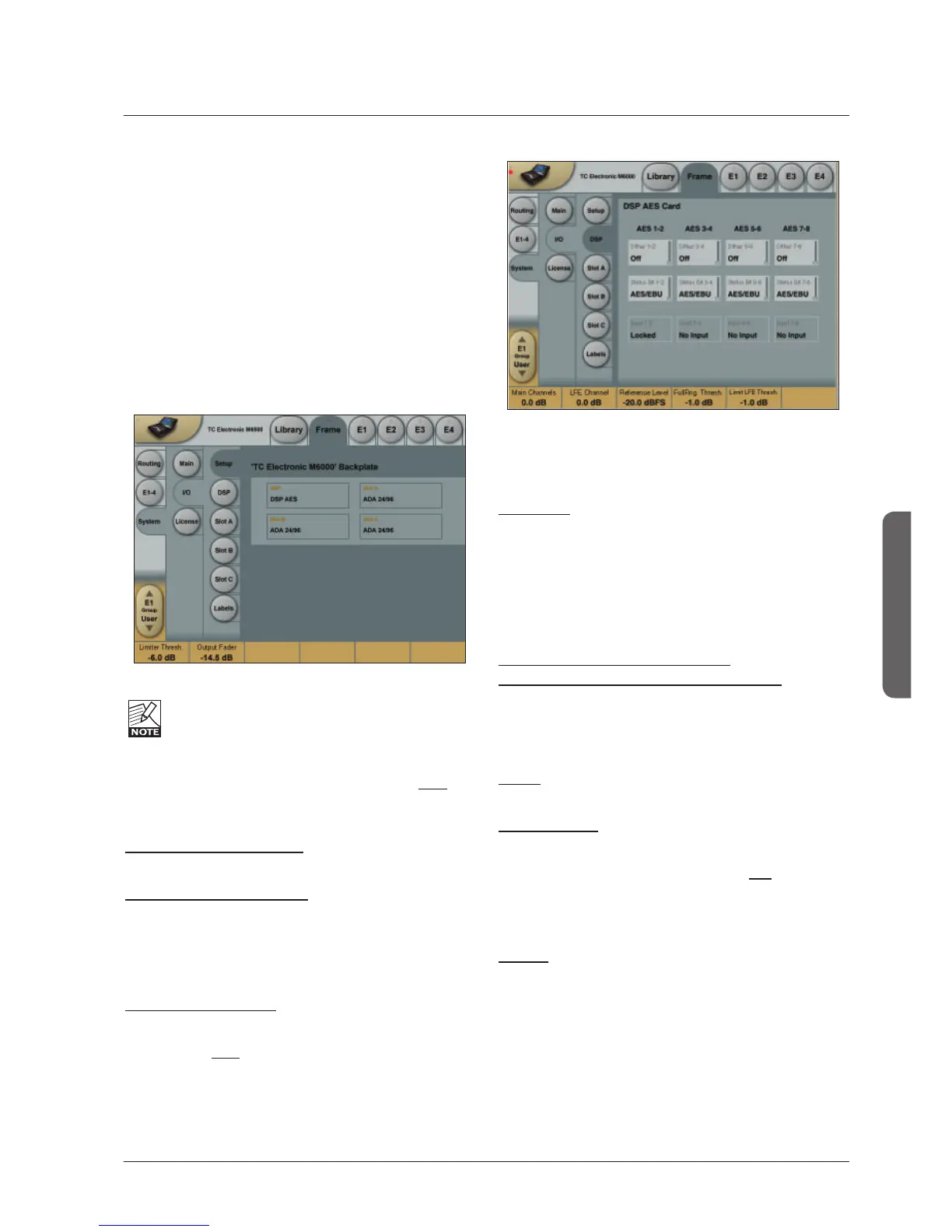
I/O - SETUP
The following Setup page will appear in: Frame/
System/I/O/Setup when an AES-8 card is installed.
The graphics are based on the card DIP switch
settings, and may not reflect the physical back panel
of the frame.
Analog Input - Digital Input
With an AES-8 card installed in a Mainframe, you must
select whether Input channels 9 through 16 should be
digital or analog.
When Digital Input is selected:
Input channels 9-16 will be the AES-8 card.
When Analog Input is selected:
2QO\DQDORJ,QSXWVDUHDYDLODEOH
If an ADA-24/96 card is installed in slot A analog Input
channels 9-10 are available.
If ADA 24/96 cards are installed in both slot A and C,
analog Input channels 9-10 and 13-14 are available.
Please note the following:
1R,QSXWVRQWKH$(6FDUGDUHDYDLODEOHZKHQDQDORJ
Input is selected.
'LJLWDO,QSXWmust be selected to activate AES-8 card
Input channels 9-16 even if no ADA 24/96 cards are
present.
2XWSXWVDUHDOZD\VDYDLODEOH,I$'$FDUGV
are installed, they will output simultaneously with the
AES-8 Outputs on channel 9-10 (Slot A) and 13-14 (Slot C).
I/O - DSP
Status Bit
Status bit information can be set separately for each of the
AES Outputs.
Options are:
$(6(%8 3URIHVVLRQDOXVDJHRI6WDWXVELWV
S/PDIF : Consumer usage of Status bits.
Dither
Range: Off, 24, 20, 18, 16, 8
Dither is set for truncation to match the receiving device.
Clock Status - Sample Slip Detection
Input 1-2, Input 3-4, Input 5-6, Input 7-8
Input 9-10, Input 11-12, Input 13-14, Input 15-16
0RQLWRUVWKH&ORFNVWDWXVRIWKHLQFRPLQJ$(6(%8
Inputs and indicates whether the incoming Clock is in sync
with the mainframe Clock settings. Three states of
incoming clock can be indicated.
/RFNHG
The Input is in sync with he Mainframe.
Sync Error (Red)
The Input is or has been out of sync with the mainframe.
Press the Reset key to see if Sample Slips are still
occurring. - If so - Check that there is only one Master
Clock source in your setup. This monitoring function is
excellent when trying to determine which connected device
is out of sync.
No Input
Indicates no connection available.
 Loading...