40
paGe Headframe sysTem - I/O
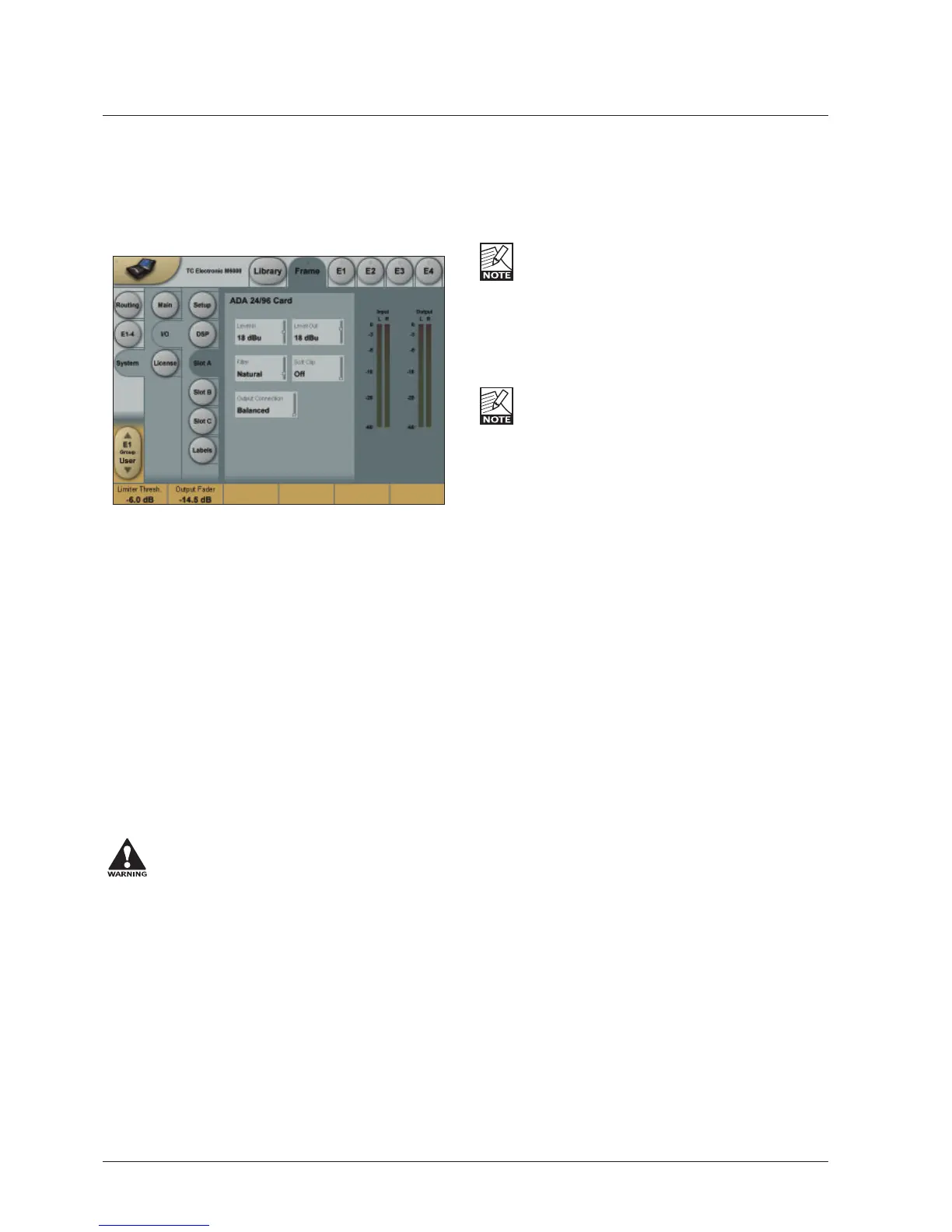
I/O - Slot A, B & C
This is where you setup card specific parameters.
Parameters are only available when a I/O Card is detected.
For the ADA 24/96 card the following parameters
can be set.
Level In
&KDQJHVWKHDQDORJQRPLQDO,QSXWOHYHOEHWZHHQG%X
DQGG%XLQG%LQFUHPHQWV
The analog Input level enables you to match the M6000
Input to the Output of e.g. your mixer. If the nominal
RSHUDWLQJOHYHORQ\RXUPL[HULVHJG%XDQG\RXVHOHFW
G%XRQWKH/HYHO,QSDUDPHWHU\RXZLOOKDYHD
KHDGURRPRIG%,I\RXVHOHFWG%XLQWKH/HYHO,QWKH
KHDGURRPZLOOEHG%DQGVRIRUWK
Level Out
&KDQJHVWKHDQDORJRXWSXWOHYHOEHWZHHQG%XDQG
G%XLQG%LQFUHPHQWV
Output Connection
Select the type of connection you are using on the Output
of the card. Select between:
%DODQFHGRUXQEDODQFHGZLWKVLJQDORQSLQRUSLQ
If you are connecting unbalanced cables to the
Outputs when Outmode is set to “Balanced”,
the Outputs will be muted/un-muted
sequentially via a gold-plated short circuit
protection relay. This is intentional and will not
cause damage to any device.
Balanced/Unbalanced Operation
Unbalanced operation
Some mastering studios prefer unbalanced wiring.
Please read these notes for optimum performance.
Preferably, balanced cables should be used on Inputs and
Outputs even for unbalanced setups.
Input
Pin 2 hot, pin 3 connected to reference (shield) at the
Output of upstream device.
Output, pin 2 selected
Pin 2 hot, pin 3 connected to reference (shield) at the Input
of downstream device. In this mode pin 3 acts as a
reference Input for the ADA2496 Output stage and should
not be left un-terminated.
This mode will not work properly with balanced
inputs unless wiring is compensated as described. If
wired properly, this is the optimum output mode for
feeding unbalanced devices.
Output, pin 3 selected
Pin 3 hot, pin 2 not needed. In this mode pin 2 and pin 1
carry the same output reference.
This works with balanced inputs using 1:1 wiring,
but balanced mode should be selected if driving a
balanced input.
Filters
When operating the mainframe in normal Sample Rates
(32 - 48kHz) you can select different down- and
up-sampling filter types. The AD and DA conversions are
always performed in high-sample domain (88.2 to 96kHz).
Afterwards the digital down- and up-sampling is performed
in the digital domain using a local DSP on the ADA24/96
card. Select filter type according to the source material you
are working on.
Filters
&KRVHEHWZHHQ/LQHDU1DWXUDO9LQWDJH%ULJKWDQG
Standard (Std).
“Linear” filter
These filters are linear-phase and non-aliasing (the
stop-band starts below the Nyquist frequency).
The pass-band response is extremely smooth and
QRQHTXLULSSOHH[WHQGLQJEH\RQGN+]:LWKWKH³/LQHDU´
filters you’ll have a hard time discriminating between the
sound of the conversion chain and direct analog, even at
N+]
“Natural” filter
%DVHGRQWKH³/LQHDU´ILOWHUFODVVEXWZLWKDFDUHIXOO\
adjusted non-linear phase response, these filters obtain
DQDOPRVW³EHWWHUWKDQOLYH´UHSURGXFWLRQRIVSDFHZKLOH
retaining crystal-clear imaging and absolute tonal neutrality.
7KH³1DWXUDO´ILOWHUVWRRDUHQRQDOLDVLQJ
“Vintage” filter
%DVHGRQWKH³1DWXUDO´ILOWHUVKHUHZH¶YHDGGHGDELW
of warmth and roundness to the treble by introducing a
VPRRWKHU³WXEHOLNH´UROORII7KLVILOWHUZRXOGEHDQ
exceptionally good choice when mastering material that
seems too hard in the high-end frequencies.
These filters too are non-aliasing and non-linear phase.
 Loading...