25
CHAPTER 2: FRONT/REAR PANEL CONTROLS AND CONNECTORS
2.1
Introduction
The
™
Power Supply series has a full set of controls, indicators
(in the standard units)
and connectors that allow the
user to set up and operate the unit. Before starting to operate the unit,
please read the following
sections for an explanation of the functions, controls and connector
terminals.
• Section 2.2: Front Panel Display and Controls.
• Section 2.3: Rear Panel Controls and Connectors.
2.2
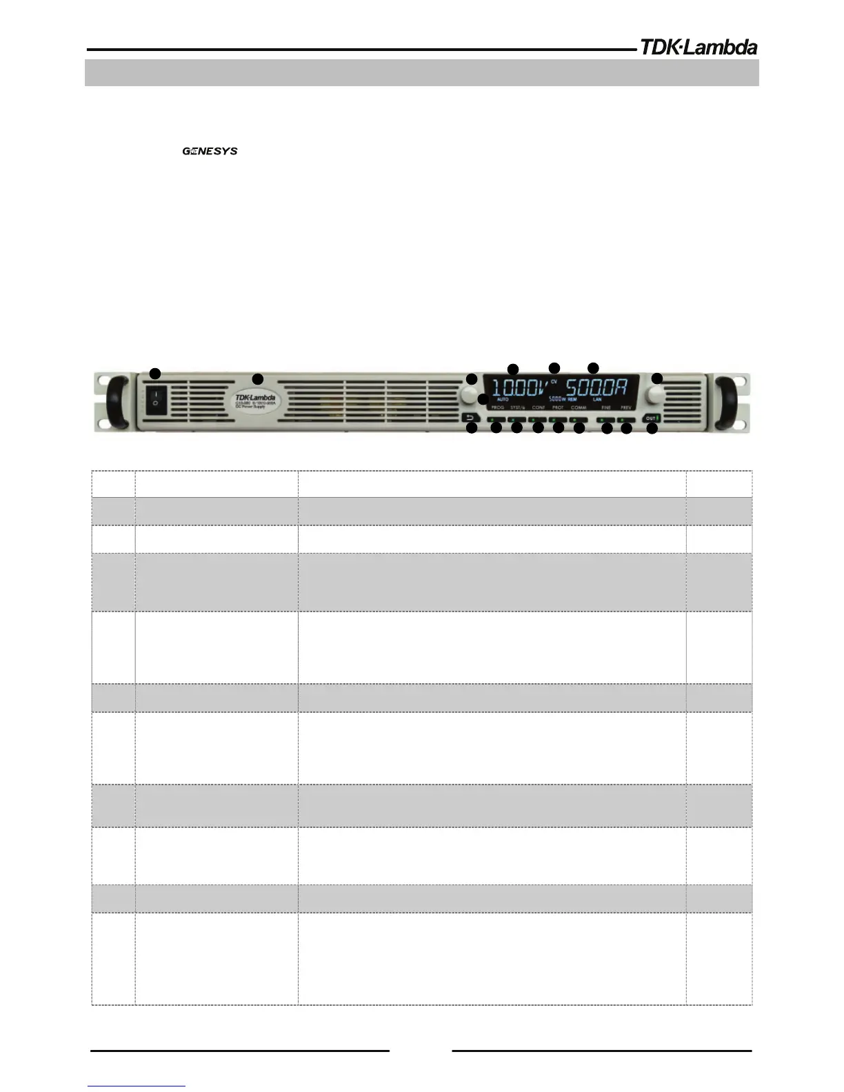
Front Panel Display and Controls
Refer to Figure 2-1and Table 2-1 for description of the Front panel controls.
Figure 2-1: Front panel controls and indicators
1 Power Switch POWER ON/OFF control
2 Power Supply Model Model, Voltage & Current Identifier
3 Voltage Encoder and
button
Encoder: High-resolution detent rotary Encoder for adjusting the
output voltage. Button: Auxiliary function to accept voltage-setting
value.
4 Voltage Display 4-digit 16-segment voltage display. Normally displays the output
voltage. In preview mode, the display indicates the program setting
of output voltage. In menu navigation, the display indicates the
selected function.
5 Operation mode indicator CV/CC/CP operation mode indicator.
6 Current Display 4-digit 16-segment current display. Normally displays the output
current. In preview mode, the display indicates the program setting
of output current. In menu navigation, the display indicates the
selected parameter.
7 Indicators bar
Refer to Fig 2.2 and Table 2.2 in the User manual for description of
the front panel indicators bar.
8 Current Encoder and
button
Encoder: High-resolution detent rotary Encoder for adjusting the
output current. Button: Auxiliary function to accept current-setting
value, select menu level & accept set parameter value.
9 BACK button Return one-step back in menu navigation mode.
10 PROG button / Indicator
Activates Program / Sequencer menu. Program menu provides
Sequencer function control, Trigger function control and load a
sequence stored inside Power Supply memory.
Green LED lights when Program menu is active. If Program menu is
active, PROG button press exits to main display.