INSTRUCTION MANUAL
HWS 3000G
TDK-Lambda
<Page>
29/49
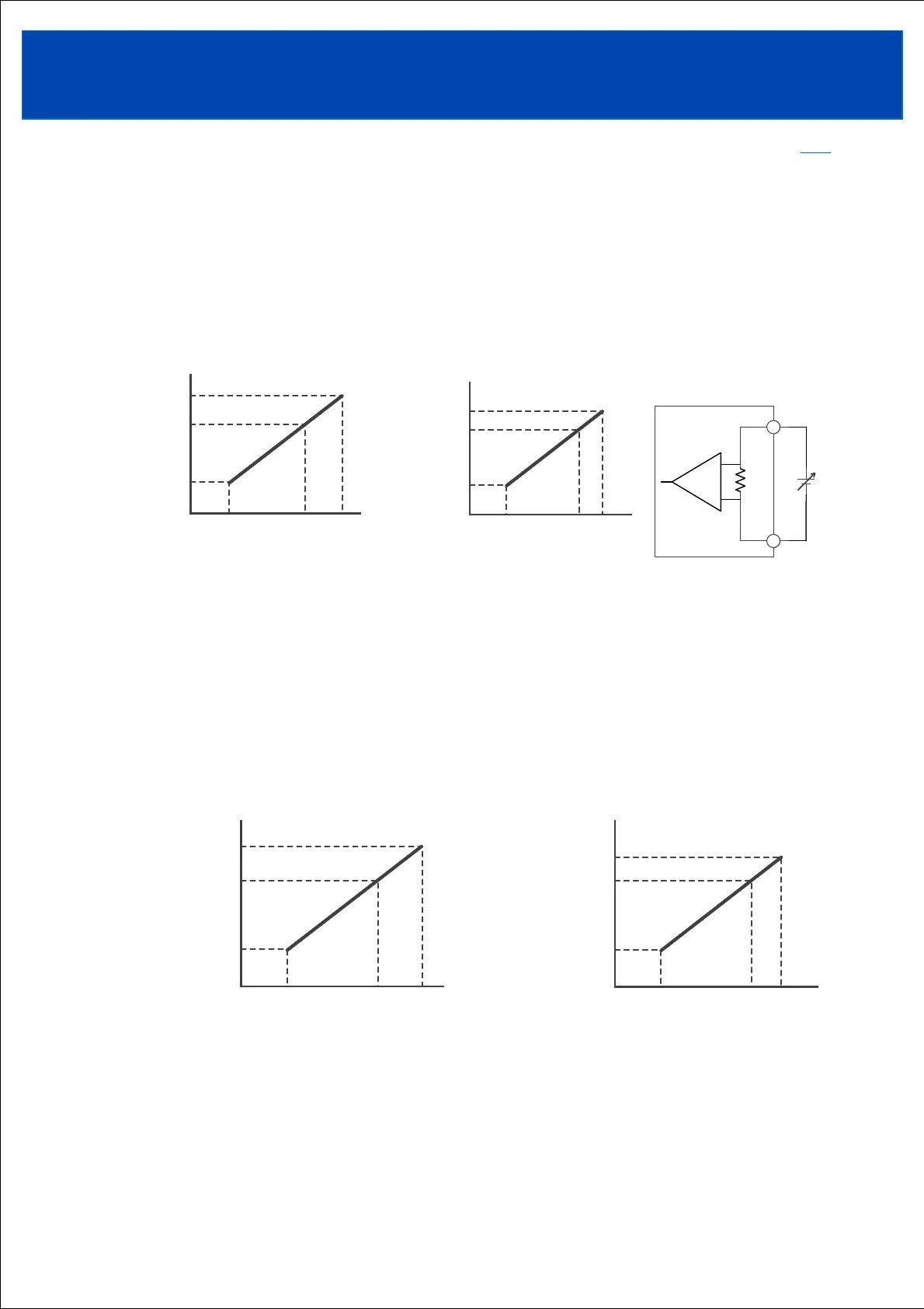
6-3-2. Variable by external power (CV terminal external voltage applied)
The constant voltage output value setting can be changed by applying an external voltage in the
range of 1-5.4V or 1-5.8V between the CV and AG terminals.
When an external voltage is applied to the CV terminal, the output voltage adjustment trimmer
setting value will be invalid.
Note that if no external voltage is applied to the CV terminal when the input is turned on, the
output voltage will be the setting value of the output voltage adjustment trimmer.
Internal resistance between CV terminal and AG terminal is 250Ω. Pay attention to the current
limit of the external voltage source.
6-3-4. Variable by communication
Constant voltage output value settings can be changed using Modbus RTU.
When communication is enabled, the output voltage adjustment trimmer and the set value by
external application to the CV terminal will be invalidated.
When communication is enabled, the output voltage setting value is maintained even if the input
voltage is cut off.
Refer to communication manual (A291-04-02_).
◆24V、130V
◆48V、60V
6-3-3. Variable by external power (CV terminal external current applied)
The constant voltage output value setting can be changed by applying an external current in the
range of 4-21.6mA or 4-23.2mA to the CV terminal.
Connect the external power supply ground to the AG terminal.
When an external current is applied to the CV terminal, the output voltage adjustment trimmer
setting value will be invalid.
Note that if no external current is applied to the CV terminal when the input is turned on, the
output voltage will be the setting value of the output voltage adjustment trimmer.
When using multiple power supplies, daisy chain connection of CV terminals is not possible.
When connecting in a daisy chain, apply external voltage to the CV terminal (Section 6-3-2).
◆24V、130V
◆48V、60V
TOPTOP
CV Voltage
Nominal
Voltage
0%
Output
Voltage
1V 5V 5.4V
Maximum
Voltage
CV Voltage
Nominal
Voltage
0%
Output
Voltage
1V 5V 5.4V
Maximum
Voltage
CV Current
Nominal Voltage
0%
Output
Voltage
4mA 20mA 23.2mA
Maximum Voltage
CV Current
Nominal Voltage
0%
Output
Voltage
4mA 20mA 23.2mA
Maximum Voltage
CV Current
Nominal Voltage
0%
Output
Voltage
4mA 20mA 21.6mA
Maximum Voltage
CV Current
Nominal Voltage
0%
Output
Voltage
4mA 20mA 21.6mA
Maximum Voltage
CV Voltage
Nominal
Voltage
0%
Output
Voltage
1V 5V 5.8V
Maximum
Voltage
CV Voltage
Nominal
Voltage
0%
Output
Voltage
1V 5V 5.8V
Maximum
Voltage
250Ω
CV
AG
250Ω
CV
AG
■Internal resistance
between CV terminal
and AG terminal