INSTRUCTION MANUAL
HWS 3000G
TDK-Lambda
<Page>
36/49
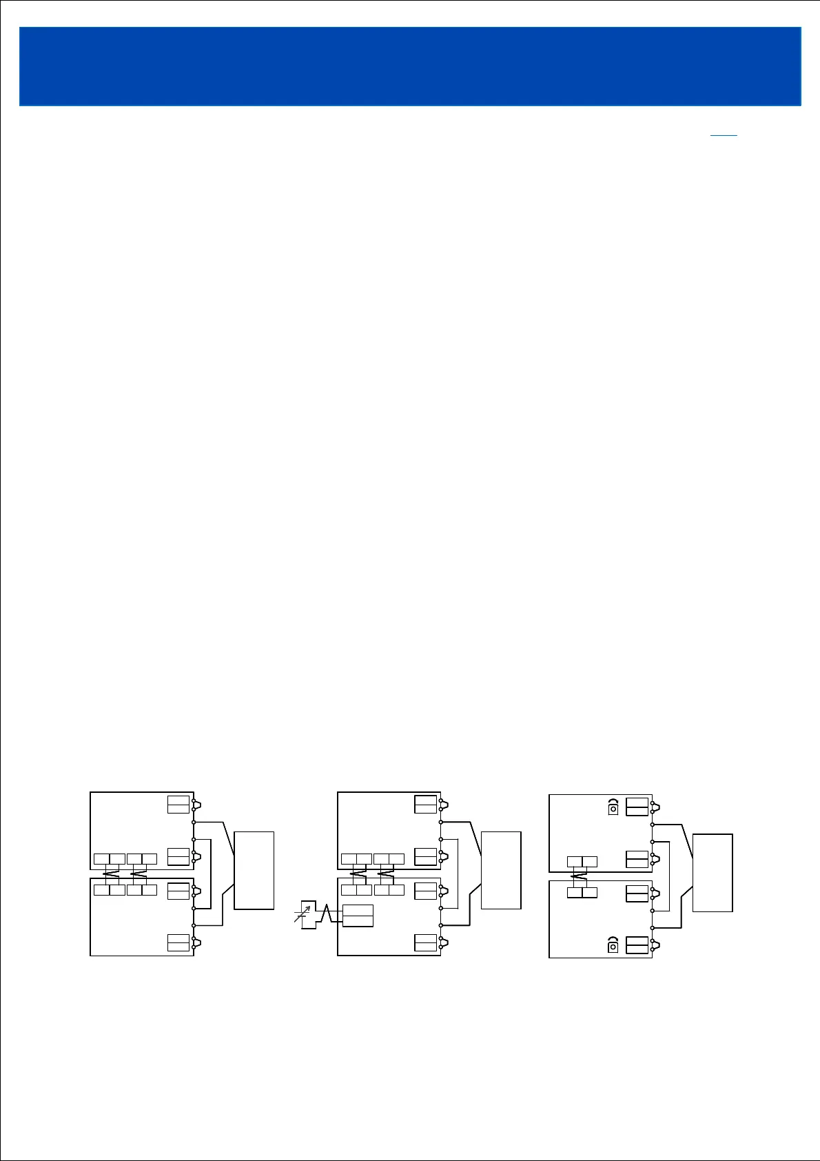
6-10. Series operation
Three types of series connection are possible: series operation for increasing output voltage, series
operation for plus/minus output, and leader-follower.
When using series-parallel connections, connect series-connected units in parallel.
6-10-1. Series operation for increasing output voltage
As a protection when one of the series-connected units stops, connect the HL to HL terminals and
DG to DG terminals between the power supplies that are operated in series. If even one power
supply stops (stops or breaks down), all remaining power supplies will be stopped.
(A) When using in constant current output mode
Connecting VB to VB terminal and AG to AG terminal, the voltage balancing function activates
and it is possible to operate in constant current output mode even during series operation.
Adjust the output voltage of each power supply to be same value within 1%.
The VB and AG terminals are isolated from the power input and output circuits.
Wire to VB terminal, AG terminal, HL terminal, DG terminal shall be as short as possible and
same length with twist.
(B) When using in constant voltage output mode
Connect the CV and AG terminals between the power supplies, and apply an external voltage
between the CV and AG terminals.
The CV and AG terminals are isolated from the power input and output circuits.
Wire to CV terminal, AG terminal, HL terminal, DG terminal shall be as short as possible and
same length with twist.
When changing the constant voltage output value using the built-in output voltage adjustment
trimmer : Connection between CV and AG terminals is not required. When using the product at a
voltage exceeding the rated voltage, be careful not to exceed the maximum output power.
・Series operation is possible up to 3 units.
・When changing the output rise speed settings (both current and voltage) using the communication
function, be sure to use the same settings for all power supplies.
TOPTOP
(A)When using in constant
current output mode
+S
+L
-L
-S
+V
-V
+S
+L
-L
-S
+V
-V
+
-
VB
AG
VB AG HL DG
HL
DG
Power
supply
Power
supply
Load
+S
+L
-L
-S
+V
-V
+S
+L
-L
-S
+V
-V
+
-
VB
AG
VB AG HL DG
HL
DG
Power
supply
Power
supply
Load
+S
+L
-L
-S
+V
-V
+S
+L
-L
-S
+V
-V
+
-
CV
AG
CV AG HL DG
HL
DG
Power
supply
Power
supply
Load
+S
+L
-L
-S
+V
-V
+S
+L
-L
-S
+V
-V
+
-
CV
AG
CV AG HL DG
HL
DG
Power
supply
Power
supply
Load
CV
AG
CV
AG
+S
+L
-L
-S
+V
-V
+S
+L
-L
-S
+V
-V
+
-
CV
AG
CV AG HL DG
HL
DG
Power
supply
Power
supply
Load
CV
AG
+S
+L
-L
-S
+V
-V
+S
+L
-L
-S
+V
-V
+
-
Power
supply
Power
supply
Load
HL
DG
HL
DG
HL
DG
HL
DG
+S
+L
-L
-S
+V
-V
+S
+L
-L
-S
+V
-V
+
-
Power
supply
Power
supply
Load
HL
DG
HL
DG
V.ADJ
H
V.ADJ
H
V.ADJ
H
V.ADJ
H
+S
+L
-L
-S
+V
-V
+S
+L
-L
-S
+V
-V
+
-
Power
supply
Power
supply
Load
HL
DG
HL
DG
V.ADJ
H
V.ADJ
H
(B) When using in constant
voltage output mode
(B) When using in constant
voltage output mode
(Using output voltage adjustment trimmer)