INSTRUCTION MANUAL
HWS 3000G
TDK-Lambda
<Page>
32/49
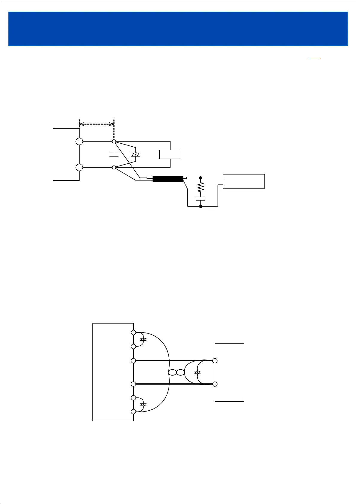
6-7. Output ripple & noise
The maximum ripple noise voltage value in the specifications is the value measured using the
measurement circuit below.
When load lines are longer, ripple will becomes larger. In this case, electrolytic capacitor,
film capacitor, etc. might be necessary to use across the load terminal.
The output ripple cannot be measured accurately if the probe ground lead of oscilloscope is too
long.
6-8. Remote sensing (+S, -S terminal)
This function compensates voltage drop of wiring from output terminals to load terminals.
Connect "+S" terminal to "+" terminal of load and "-S" terminal to "-" terminal of load with
sensing wires.
The total line voltage drop (+ side line and - side line) shall be less than 0.3V.
In case that sensing line is too long, we recommend connecting electrolytic capacitors at the
following locations:
1) Across the load terminals,
2) Between “+S” terminal and “+L” terminal,
3) Between "-S" terminal and "-L" terminal.
When not using the remote sensing function, short-connect the "+S" and "+L" terminal, and the
"-S" and "-L" terminal.
Power
Supply
+S
+L
-L
-S
+
-
Load
++
++
++
+V
-V
Power
Supply
+S
+L
-L
-S
+
-
Load
+
+
+
+V
-V
TOPTOP
Coaxial Cable
1.5 m 50
Ω
C2
+
Load
+
-
150mm
C1
R1
C3
Oscilloscope
Power
Supply
Bandwidth : 100 MHz
C1 : 0.47uF Cap., Film
C2 : 100uF Cap., Elect.
C3 : 4700pF Cap., Ceramic
R1 : 50Ω
Coaxial Cable
1.5 m 50
Ω
C2
+
Load
+
-
150mm
C1
R1
C3
Oscilloscope
Power
Supply
Bandwidth : 100 MHz
C1 : 0.47uF Cap., Film
C2 : 100uF Cap., Elect.
C3 : 4700pF Cap., Ceramic
R1 : 50Ω