INSTRUCTION MANUAL
HWS 3000G
TDK-Lambda
<Page>
42/49
6-18. Input voltage shortage alarm (ACF signal)
It detects that the input voltage is cut off and the ACF signal becomes High.
When the power supply output power is 20% or more, the time from the input cutoff state until the
signal becomes High is 15ms or less.
This time may change if the power supply output power is less than 20% of maximum or if the input
voltage is distorted.
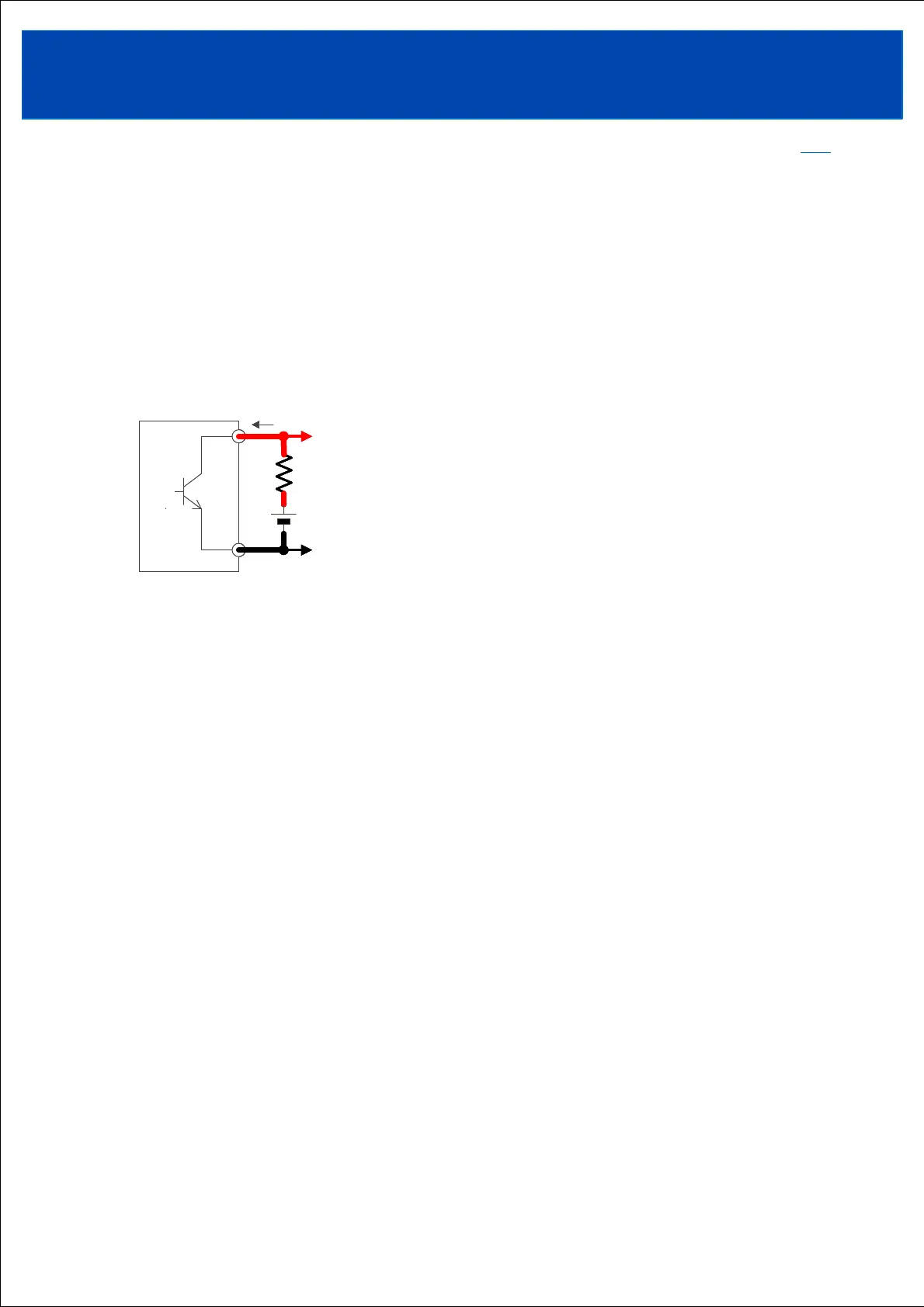
The ACF signal is an open collector output, and the emitter is connected to the DG terminal.
ACF signal may also be output in the following cases
・When the input voltage falls below the specifications
6-19. Communication function
Built-in communication function using RS-485 interface.
Using the Modbus-RTU protocol, it is possible to monitor the power supply operating status and change
various settings.
When communication is enabled, various setting values are retained even if the input voltage is cut off.
Additionally, information such as cumulative operating time and product information is recorded in
internal non-volatile memory, so it can be retained even if the input voltage is cut off.
Refer to the communication manual for details.
<Communication function example>
・monitoring :Power supply operating status can be read.
ex. Output voltage, output current, power supply ambient temperature, various
protection operations, etc.
・Display log :Operation history can be read.
ex. Cumulative operating time, protection operation history, input voltage shortage
alarm, etc.
・Setting value change :Output voltage and output current settings can be changed.
Real-time control of constant voltage output setting value and constant current
output setting value is also possible.
The output rise time can also be changed.
・Output ON/OFF :Output ON/OFF can be controlled while maintaining the input application state.
・Product information :Product information can be read
ex. Model name, serial number, lot number, firmware version, etc.
・communication settings :Address, communication speed, parity bit, and stop bit can be set.
TOPTOP
ACF signal output
Vex
Rex
Signal ground
Sink current
Iex
ACF signal output
Vex
Rex
Signal ground
Sink current
Iex
ACF
DG
ACF signal output
Vex
Rex
Signal ground
Sink current
Iex
ACF
DG
Requires a limit on sink current Iex.
Select Vex and Rex so that Iex is within the range of
0.1 to 20mA using the formula below.
Vex is 1V or more and 30V or less.
Iex = ( Vex – 0.3 ) / ( Rex )