24
83-530-000 Rev J
2. SPECIFICATION
All specifications are subject to change without notice.
Contact factory for specific model availability.
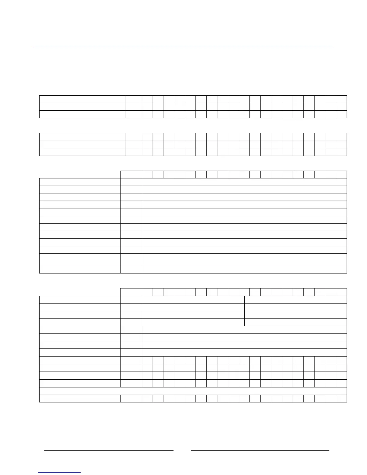
2.1. OUTPUT RATING (Duty Cycle Continuous Duty).
2.1.1. Standard Models – 10kW
1. Rated output Voltage V 7.5 10 12.5 20 25 30 40 50 60 80 100 125 150 200 250 300 400 500 600
2. Rated Output Current A 1000 1000 800 500 400 333 250 200 167 125 100 80 66 50 40 33 25 20 17
3. Rated Output Power kW 7.5 10.0 10.0 10.0 10.0 10.0 10.0 10.0 10.0 10.0 10.0 10.0 9.9 10.0 10.0 9.9 10.0 1.0 10.2
2.1.2. Standard Models – 15kW
1. Rated output Voltage V N/A N/A N/A N/A N/A N/A N/A N/A 60 80 100 125 150 200 250 300 400 500 600
2. Rated Output Current A 250 187.5 150 120 100 75 60 50 37.5 30 25
3. Rated Output Power kW 15.0 15.0 15.0 15.0 15.0 15.0 15.0 15.0 15.0 15.0 15.0
2.2. INPUT CHARACTERISTICS
V 7.5 10 12.5 20 25 30 40 50 60 80 100 125 150 200 250 300 400 500 600
1. Input voltage/freq. (range) --- 208VAC (180-253), 400 VAC (360-440), 480 VAC (432-528), all 47-63Hz
2. No of phase --- 3 Phase (Wye or Delta) 4 wire total (3 Phase and 1 protective earth ground)
3. Dropout voltage V 175/355/425
4. Input current 180/360/432 VAC A 10kw – 45/23/20 15kw – 64/32/27 All at full rated output power.
5. Power Factor --- 0.88 Passive
6. Efficiency at Low Line, 100% load % 77min for 7.5kw, 83 min for 10kw, 88 min for 15kw
7. Inrush current A Not to exceed full rated input current See Para 2.4
8. Leakage current mA 3.5 (EN60950-1) max
9. Input Protection --- 208 Circuit Breaker, 400/480 Line Fuse
10. Fuse --- 400/480 Input Only
11. Input Overvoltage Protection Unit shall not be damaged by line overvoltage with max. duration of 100uSec. Up to 120% of nominal AC
input voltage.
12. Phase Imbalance % = <5% on Three Phase Input
2.3. STATIC CHARACTERISTICS
V 7.5 10 12.5 20 25 30 40 50 60 80 100 125 150 200 250 300 400 500 600
1. Max. line regulation c.v --- 0.1% of FS from lo min. to lo max 0.01% of FS from lo min. to lo max
2. Max. line regulation c.c --- 0.1% of FS from Vo min. to Vo max 0.05% of FS from lo min. to lo max
3. Max load regulation c.v --- 0.1% of FS from lo min. to lo max 0.02% of FS lo min. to lo max
4. Max load regulation c.c --- 0.1% of FS from Vo min. to Vo max 0.075% of FS from Vo min. to Vo max
5. Temp. drift c.v --- +/-0.05% of Full Scale over 8 hours, after 30 minute warm up, constant Line, Load & Temperature
6. Temp drift c.c --- +/-0.05% of Full Scale over 8 hours, after 30 minute warm up, constant Line, Load & Temperature
7. Stability c.v PPM/C 200 (0.02% Full Scale)/Degree C
8. Stability c.c PPM/C 300 (0.03% Full Scale)/Degree C
9. Output noise p-p (20MHz) c.v mV 60 60 60 60 60 60 60 75 75 100 100 125 135 135 200 200 200 300 350
10. Ripple r.m.s 5Hz1MHz c.v
mV 20 20 20 20 20 20 20 20 20 25 25 25 25 35 35 60 60 60 60
11. Ripple r.m.s 5Hz1MHz c.c (10kW)
mA 5100 5100 2600 2600 1700 1700 100 80 67 50 40 32 20 20 16 13 10 8 7
12. Ripple r.m.s 5Hz1MHz c.c(15kW)
mA - - - - - - - - 100 100 100 50 50 20 20 20 10 10 10
*Ripple and Noise at Full Rated Voltage & Load at 25C, Nominal Line. For models not listed use the ripple limit of the next higher voltage model. Per EJ RC9002A.
13. Rem. sense compensation/wire V 1 1 1 1 1 1.5 2 3 3 4 5 5 5 5 5 5 5 5 5