70
83-530-000 Rev J
8.2.5. Setting the Unit into Remote or Local Mode
The unit will be put into Remote mode only via serial communication command.
Commands that will put the unit into Remote mode are:
RST PV n RMT n
OUT n PC n
(for n values see Tables 7-4, 7-5 and 7-6)
There are two Remote modes:
a) Remote: In this mode, return to local can be made by the front panel REM/LOC or via
serial port command RMT 0. Set the unit into Remote mode via serial port RMT 1
command.
b) Local Lockout: In this mode the unit can be returned to Remote mode via the serial
port RMT 1 command or by turning off the AC power until the display turns off and
then recycling AC power. In local Lockout mode, the front panel REM/LOC button is
not active. Set the unit into Local Lockout mode via serial port RMT 2 command.
8.2.6. RS232/485 Port in Local Mode
When the power supply is in local mode, it can receive queries or commands. If a query
is received, the power supply will reply and remain in Local mode. If a command that
affects the output is received, the power supply will perform the command and change to
Remote mode.
8.2.7. Front Panel in Remote Mode
Front panel control in Remote mode is disabled except for:
1. PREV: use to preview the Voltage and Current limit setting.
2. OVP/UVL: use to preview the OVP/UVL setting.
3. LOC/REM: use to set the unit into Local mode.
In Local Lockout mode, only PREV and OVP/UVL are active.
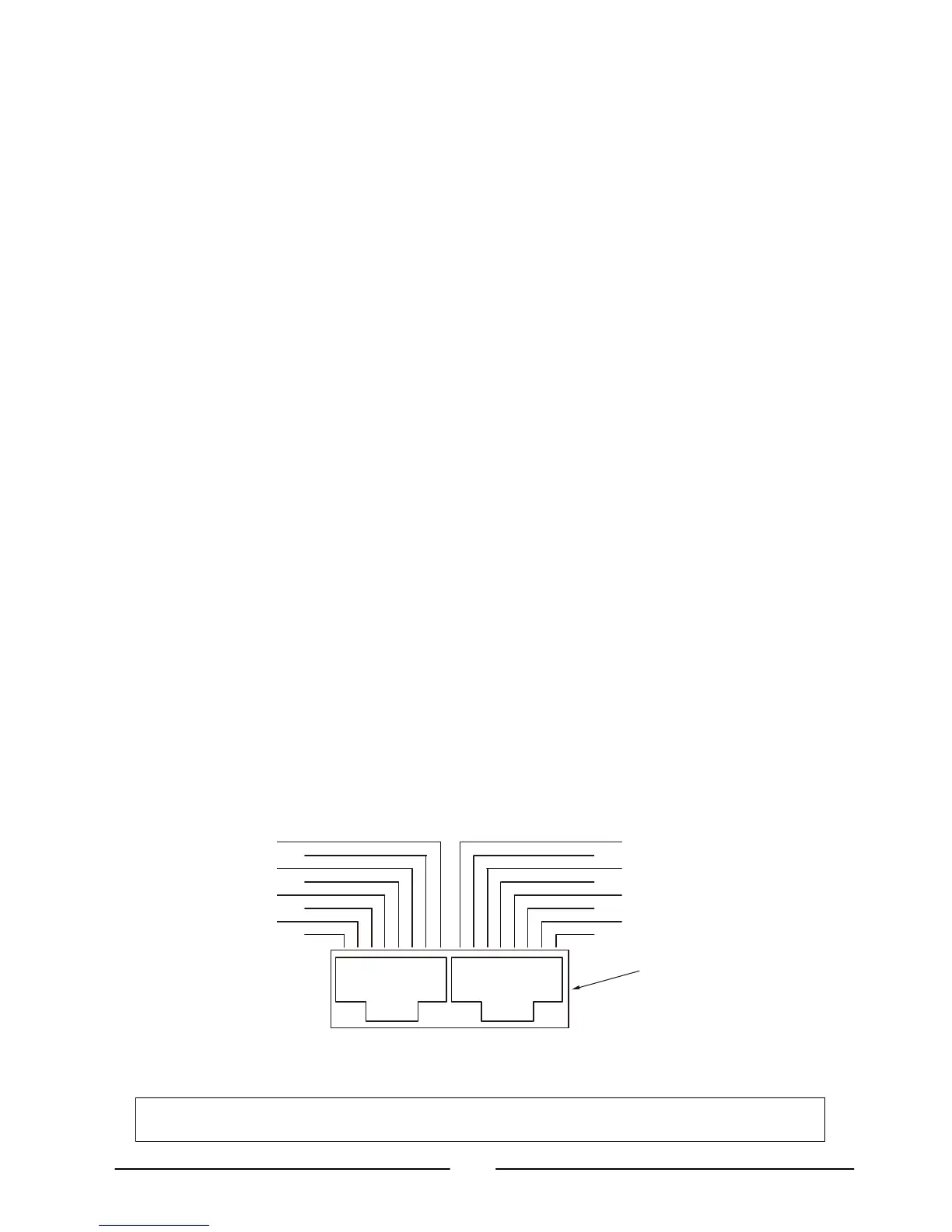
8.3. Rear Panel RS232/485 Connector
The RS232/485 interface is accessible through the rear panel RS232/485 IN and RS485
OUT connectors. The connectors are 8 contact RJ-45. The IN and OUT connectors are used
to connect power supplies in a RS232 or RS485 chain to a controller. Refer to Fig. 8-1 for
IN/OUT connectors.
Tx and Rx are used for RS232 communication. Txd +/- and Rxd +/- are used for RS485
communication. Refer to RS232 and RS485 cable description for connection details.
NC
NC
RX
NC
NC
TXD
RXD
TXD
RXD
RXD
TXDRXD
TXD
SG
SG
-
-
-
-
TX
OUT
(connector enclosure)
1: Rear panel J3 IN/OUT connectors pinout