72
83-530-000 Rev J
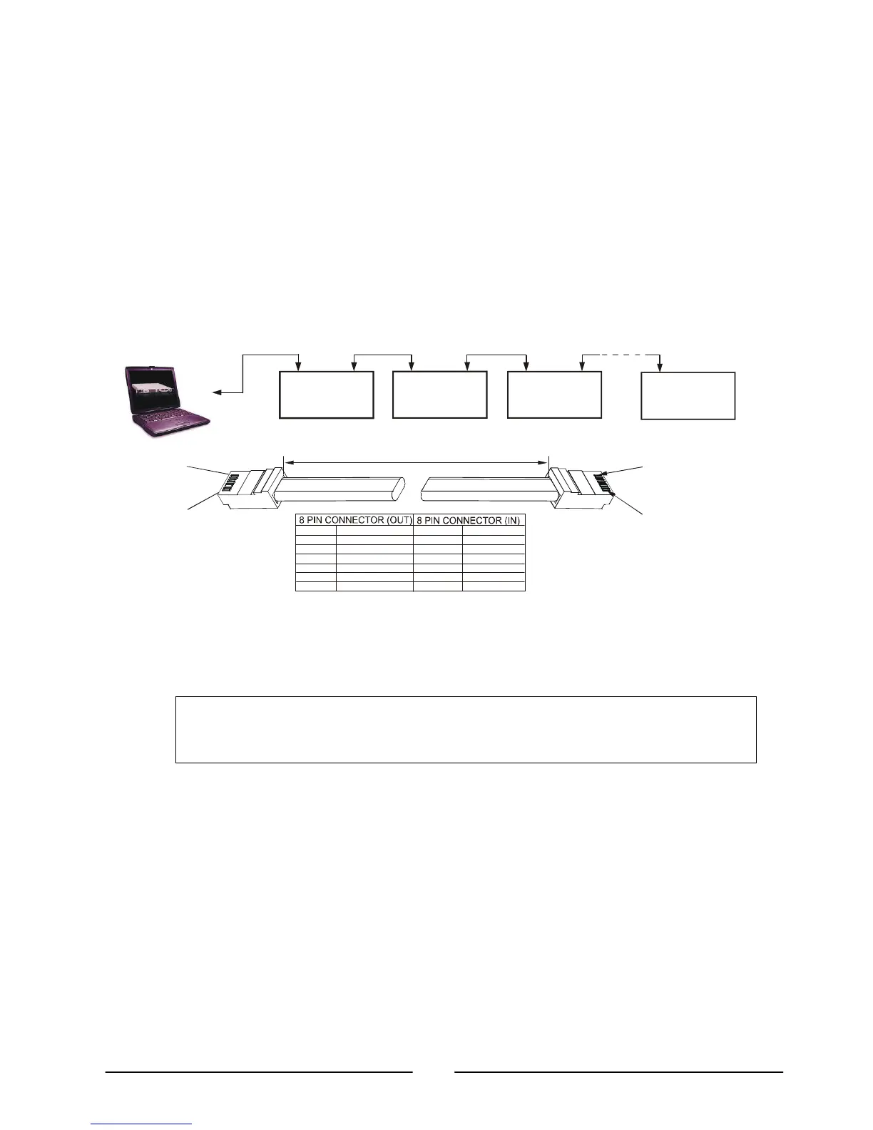
8.4.2. Multi Power Supply Connection to RS232 or RS485 Bus
Up to 31 units can be connected to RS232 or RS485 bus. The first unit connects to the
controller via RS232 or RS485 and the other units are connected with RS485 bus.
a) First unit connection: Refer to Section 8.4.1 for connecting the first unit to the
controller.
b) Other units connection: The other units on the bus are connected via their RS485
interface.
Refer to Figure 8-5 for typical connection.
Set rear panel setup switch SW1-6 to its UP position.
Using the Linking cable (Refer to Fig. 8-6), connect each unit OUT connector to
the next unit IN connector.
8.5. Communication Interface Protocol
8.5.1. Data format
Serial data format is 8 bit, one start bit and one stop bit. No parity bit.
NOTE
The address (“ADR n”) command must return an “OK” response before any other
commands are accepted.
8.5.2. Addressing
The Address is sent separately from the command. Refer to section 8.7.3 for details.
8.5.3. End of Message
The end of message is the Carriage Return character (ASCII 13). The power supply
ignores the Line Feed (ASCII 10) character.
8.5.4. Command Repeat
The backslash character “\” will cause the last command to be repeated.
OUT
POWER SUPPLY
#1
OUT
POWER SUPPLY
#2
OUT
POWER SUPPLY
#3
OUT
#31
RS232/RS485
RS485 RS485
RS485
Fig 8-5: Multiple power supply RS232/485 connection
8
1
1
8
1
6
3
5
4
1
6
3
5
4
PIN NO.
HOUSING HOUSING
PIN NO.NAME
NAME
SHIELD
SG
TXD
TXD
RXD
RXD
SHIELD
SG
RXD
RXD
TXD
TXD
-
-
-
-
6: Serial link cable with RJ
45 shielded connectors (P/N: GEN/RJ
L=0.5m typ.