46
83-530-000 Rev J
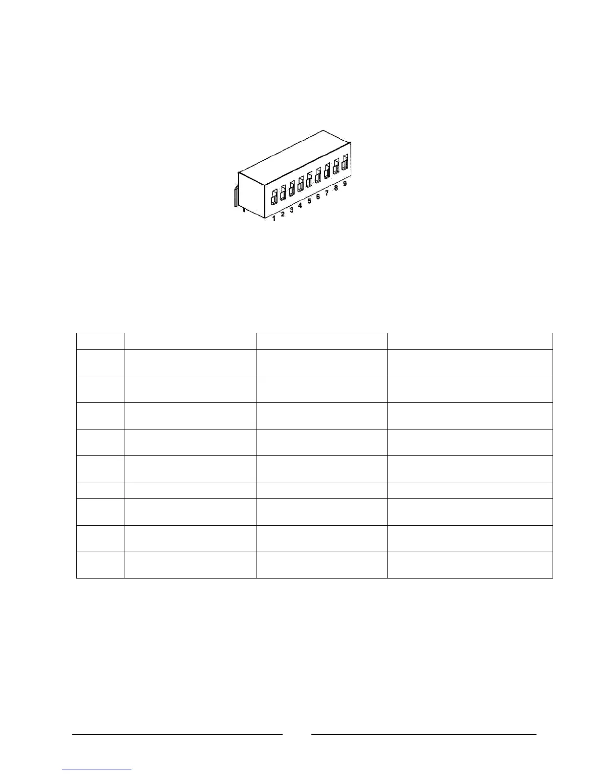
4.3. Rear Panel SW1 Setup Switch
The SW1 Setup switch (see Fig.4-3) is a 9-position DIP switch that allows the user to choose
the following:
Fig. 4-3: SW1 setup DIP switch
4.3.1. SW1 Position Function
Refer to Table 4-3 for description of SW1 position functions. The factory default setting is
Down for all positions. Observe ESD precautions when setting switch positions.
Table 4-3: SW1 Positions Functions
Position Function DOWN (Factory default) UP
SW1-1 Output Voltage remote
Analog programming
Output Voltage
Programmed by Front Panel
Output Voltage
programmed by remote analog voltage
SW1-2 Output Current remote analog
programming
Output Current
programmed by Front Panel
Output Current
programmed by remote analog voltage
SW1-3 Programming range select
(Remote voltage/resistive)
0-5V (0-5Kohm) 0-10V (0-10Kohm)
SW1-4 Output Voltage and
Current Monitoring Range
0-5V 0-10V
SW1-5 Shut-Off Logic select Off: Low (0-0.6V) or Short
On: High (2-15V) or Open
Off: Low (2-15V) or Open
On: High (0-0.6V) or Short
SW1-6 RS232/485 select RS232 interface RS485 interface
SW1-7 Output Voltage
resistive programming
Output Voltage
programmed by Front Panel
Output Voltage
programmed by external resistor
SW1-8 Output Current
resistive programming
Output Current
programmed by Front Panel
Output Current
programmed by external resistor
SW1-9 Enable/Disable control Rear panel Enable/Disable
control is not active
Rear panel
Enable/Disable control is active
4.3.2. Resetting the SW1 switch
Before making any changes to the SW1 switch setting, disable the power supply output
by pressing the front panel OUT button. Ensure that the output voltage falls to zero and
OUT LED is off. Then use any small flat-bladed screwdriver to change the SW1 switch
setting.