1904/2019 - EN/V9 Technetix Group Limited
Product user manual
DBE-1200S
4. Ensure that all RF output ports in use are connected to a 75 Ω terminated load to prevent reflections aecting the
RF spectrum analyzer readings for commissioning levels. Connect a spectrum analyzer to the -20 dB output test
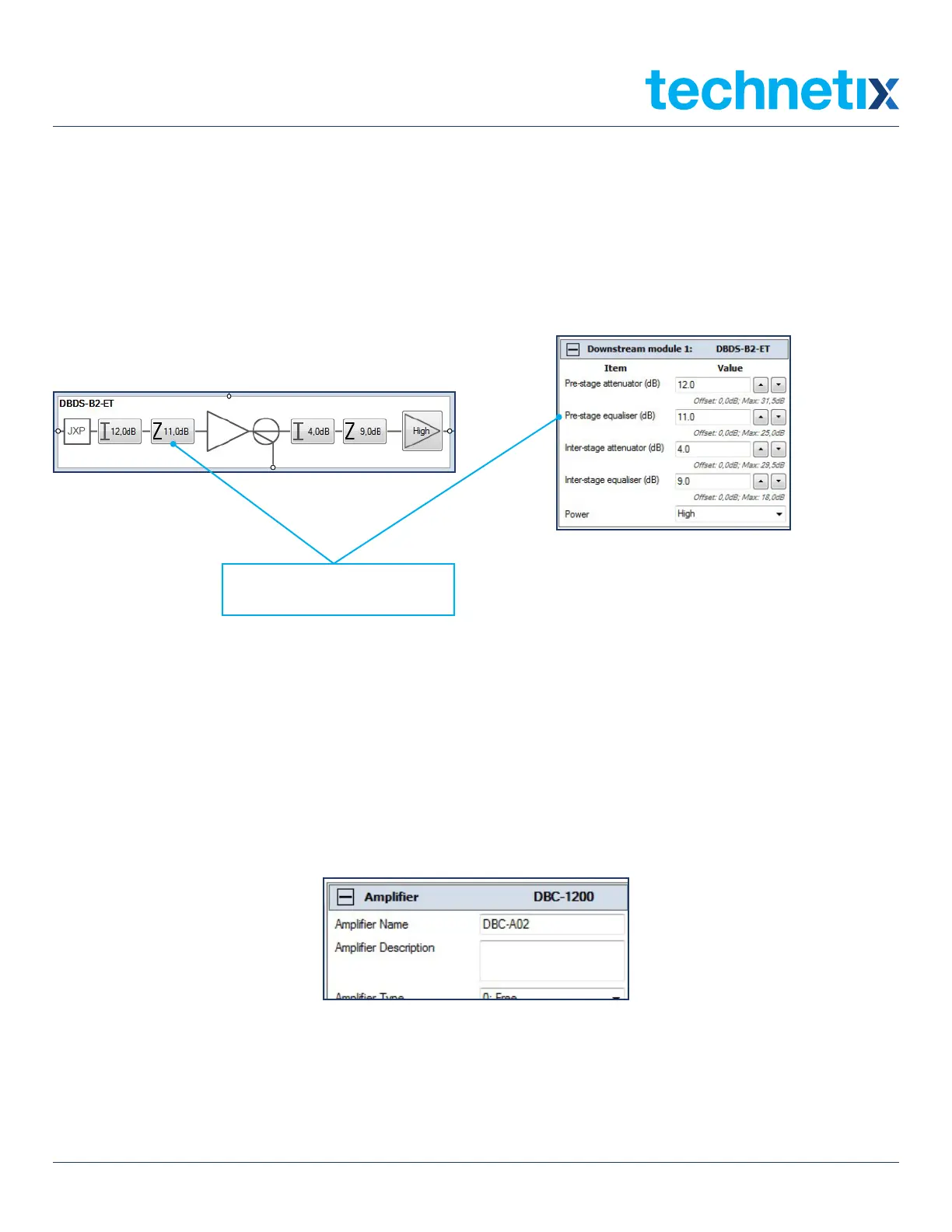
point. Read the pilot frequency levels and set them to the network design/system levels required by adjusting
the pre-stage equalizer first to obtain the correct pilot tilt/slope value as required in the network/system design
documentation. Remember, once a value is set in the Pre-stage equalizer field, the amplifier schematic, or the
parameter view table to the right of the application screen, click on Send to amp to set these values electronically.
Then check the tilt/slope between the pilot frequencies on the spectrum.
Pre-stage equalizer (dB)
5. Next set the pilot frequencies’ levels to the network/system design levels by changing the Pre-stage attenuator
values in the amplifier tab schematic or parameter view table. Remember to click on Send to amp after changing the
values in the BLL application and check that the levels are correct on the RF spectrum analyser.
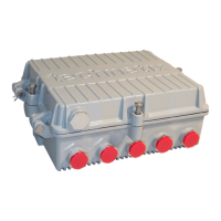
6. Once the amplifier downstream/forward is commissioned, the software values can be recorded on the PSU lid label
using a fine tip permanent marker pen. They can also be saved electronically.
To save the amplifier settings electronically, enter the amplifier ID number into the Amplifier name field as shown below.