,
'.. SCHEMATIC DIAGRAM (Parts list on pages 59---64.)
. (This schematic diagram may be modified at any time with the development of
new technology.)
Note1:
. S601:Voltageselector in "240V" position. (For [GC]area only.) (110V
<-> 127V <-> 220V <-> 240V)
.Resistance are in ohms (0), 1/4 watt unless specified otherwise.
1 K=1,OOO (0),1 M=1,OOOk (0)
. Capacity are in micro-farads (1lF)unless specified otherwise.
.Allvoltage values shown in circuitry are under no signal condition and playback mode with
volumecontrol at minimum position otherwise specified.
( )
Voltagevaluesat recordmode.
Formeasurement us EVM.
. Importantsafety notice
Components identified by .6 mark have special characteristics important for safety.
When replacing any of these components, use only manufacturer's specified parts.
.(-:::+B>-) indicates +B (bias).
.(...IO(-B:>OO...) indicates -B (bias).
. ( ,.,..""."",."",y.) indicates the flowof the playback signal.
. ( c::==> ) indicates the flowof the record signal.
.Thesupply part number is described alone in the replacement parts list,
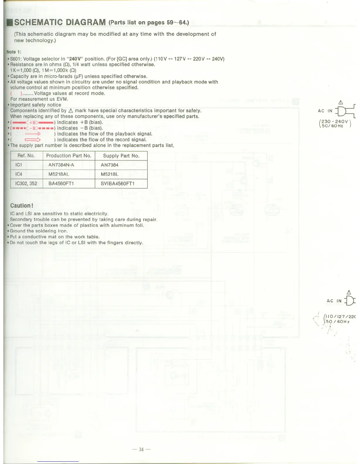
.:t
ACIN~
(
230 - 240V
)
50/60 Hz
Caution!
ICandLSIare sensitive to static electricity.
Secondarytroublecan be prevented bytaking care during repair.
.Coverthe parts boxes made of plastics with aluminum foli.
.Groundthe soldering iron.
I Puta conductive mat on the work table.
.Donot touch the legs of IC or LSI with the fingers directly.
.:t
AC IN V
~ (11O/127/22C
\50/60Hz
1\,:,;
. i\.
- 34-
Ref. No.
Production Part No.
Supply Part No.
IC1
AN7384N-A AN7384
IC4 M5218AL M5218L
IC302,352
BA4560FT1
SVIBA4560FT1