lRS.TR9~
.MEASUREMENTS AND ADJUSTMENTS
Measurement Condition
. Rec. level control; Maximum
. Timer switch; Off
. Recording-balance control; Center
. Bias-adjustment control; Center
. Reverse-mode selector switch; +z
. Tape-to-tape recording-speed switch; Off
.Dolby NR switch; Off
. ATC switch; Off
. Make sure heads are clean
. Make sure capstan and pressure roller are clean
.Judgeable room temperature 20:tSC (68:t9°F)
Measuring instrument
.
EVM (Electronic Voltmeter)
. Oscilloscope
. Digital frequency counter
. AF oscillator
. ATT (Attenuator)
.DC voltmeter
. Resistor (6000)
Test tape
.Head azimuth adjustment (8kHz, -20dB); QZZCFM
.Tape speed adjustment (3kHz,-10dB); QZZCWAT
. Playback frequency response(315Hz, 12.5kHz, 10kHz,
8kHz, 4kHz, 1kHz,250Hz, 125Hz,63Hz, -20dB);
QZZCFM
.Playback gain adjustment (315Hz, Ode); QZZCFM
.Overall gain adjustment and Overall frequency response
Normal reference blank tape; QZZCRA
CrO2 reference blank tape; QZZCRX
Metal reference blank tape; QZZCRZ
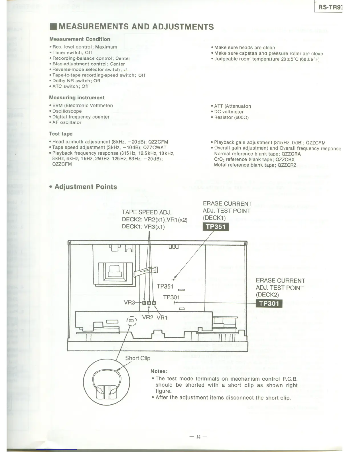
. Adjustment Points
TAPE SPEED ADJ.
DECK2: VR2(x1),VR1 (x2)
DECK1: VR3(x1)
ERASE CURRENT
ADJ. TEST POINT
(DECK1)
B
TP301
ERASE CURRENT
ADJ. TEST POINT
(DECK2)
VR3
811>7,
=
VR2 VR1
Notes:
. The test mode terminals on mechanism control P.C.B.
should be shorted with a short clip as shown right
figure.
. After the adjustment items disconnect the short clip.
-14-