EasyManuals Logo

TechnipFMC Smith Meter microLoad.net User Manual

TechnipFMC Smith Meter microLoad.net
46 pages
To Next Page IconTo Next Page
To Previous Page IconTo Previous Page
Page #31 background imageLoading...
Page #31 background image

Section IV – Diagrams
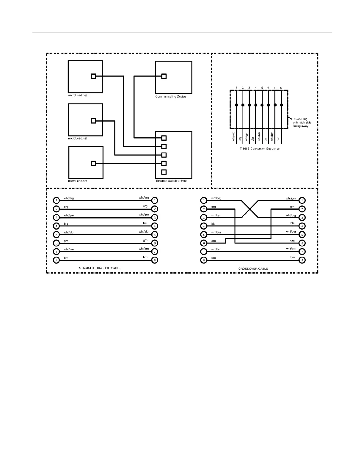
Figure 18. microLoad.net Ethernet Communications
microLoad.net RJ-45 Terminations
The microLoad.net and the associated RJ-45 connector located in the MNET board is designed as an “Ethernet
Device”. When connecting to a distributive system through an Ethernet switch/hub or wireless bridge, a straight
through T-568B cable is utilized. When interfacing directly to a PC, a crossover cable must be utilized (i.e. a crossover
cable is used only when connecting two Ethernet devices together without the use of a hub, switch and/or router).
Eight conductor CAT 5 cable contains (4) four pairs of wires. Each pair consists of a solid (or predominantly) colored
wire and a white wire with a stripe of the same color. These pairs are twisted together. When making up a connector,


󰀨-
tion. The orange and green pairs are designated for 10BaseT Ethernet. The brown and blue pairs are not used in
the microLoad.net.
Note: The odd pin numbers are always white with a colored stripe.

Table of Contents

Questions and Answers:

Question and Answer IconNeed help?

Do you have a question about the TechnipFMC Smith Meter microLoad.net and is the answer not in the manual?

TechnipFMC Smith Meter microLoad.net Specifications

General IconGeneral
BrandTechnipFMC
ModelSmith Meter microLoad.net
CategoryControl Unit
LanguageEnglish

Related product manuals