Section II – Pre-Installation Considerations
An important pre-installation consideration is the se-
lection of the ancillary equipment to be used with the
microLoad.net and how that equipment is interfaced.
(Table 6, page 16) which will assist in the assignment
of devices to the microLoad.net’s various I/O positions.
The Worksheet lists the available I/O points versus
possible devices or functions which may be applied.
By checking the appropriate boxes on the Worksheet
I/O map of your application is established. A sample
application starts on page 40.
Mechanical
In addition to the following, all previous warnings and
cautions should be reviewed before installation.
1. A solid vertical or slanted surface should be used
for mounting the explosion-proof microLoad.net
housing.
2. The location and the height of microLoad.net should
be selected to permit easy viewing of the display
and to provide convenient access to the keypad
by all users. See Figure 2 for dimensions of the
microLoad.net.
cover. For service, wiring and removal of parts the cover
must removed.
4. Conduit entry to the explosion-proof microLoad.net
is both through the bottom and sides. There are two
the unit.
5. In warm climates, microLoad.net should be shaded from
direct sunlight. The maximum external temperature
of the microLoad.net housing must not exceed 140°F
(60°C) to ensure that the internal temperature limit is not
exceeded.
Electrical
Note: See Appendix A for information regarding ATEX electrical
installation.
1. All DC wiring must be routed into microLoad.net
through the conduit entries located in the bottom of
the housing. Do not route DC and AC wiring through
the same conduit entry.
2. The DC signal wires must be multi-conductor
shielded cable of 18 to 24 AWG minimum stranded
copper.
at a minimum. Direct Ethernet connections between
computer and microLoad.net require a crossover
-
ration is used where the microLoad.net units are
networked through a hub or switch.
Note: The following recommendations are based on our knowledge
of the electrical codes. The local electrical codes should be reviewed
to ensure that these recommendations follow the local code. Also
installation manuals of all the equipment being wired into the micro-
Load.net should be reviewed for transmission distances and wire
recommendations.
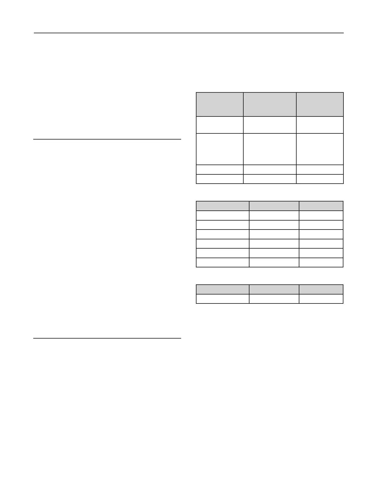
Table 1. Typical Wire Sizes
Equipment Number & Gauge
of Wire
Belden
Number or
Equivalent
Transmitters
4 / 18 Ga.
4 / 20 Ga.
9418
8404
Temp. Probes
Density and
Pressure
ransmitters 4 / 22 Ga.
8729
OR
9940
EIA-485 Comm 4 / 24 Ga. 9842
Table 2. Maximum Cable Length and Baud Rate (EIA-232)
Baud Rate Feet Meters
250 75
19,200 500 150
9,600 1,000
4,800 2,000 610
2,400 4,000 1,220
1,200 4,000 1,220
Table 3. Maximum Cable Length and Baud Rate (EIA-485)
Baud Rates Feet Meters
4,000 1,220
4. All AC wiring must be routed into microLoad.net
through the conduit entries located in the side of
the housing. Connectors sized for a maximum of 14
gauge wire, consult the local electrical codes for the
minimum AC wire size required for your application.
Do not route AC and DC wiring through the same
conduit entry.
5. All AC wiring should be stranded copper and must
comply with federal, state and local codes and
6. Two separate AC circuits must be provided from
the breaker panel. One circuit will supply isolated
power to the microLoad.net electronics (instrument
power). The second circuit will supply power to the
external devices.
7. For proper operation, the microLoad.net must be