English
7
Hydraulic diagrams
The entire instruction manual with all schemes and programs can be downloaded
from: www.ta.co.at section DOWNLOADS
Pump valve system of the programs 49, 177, 193, 209, 225, 226, 227, 417, 625:
Speed control (if activated):
Control output COP 1: The speed control only operates when filling tank 1. If max1 is
exceeded on the sensor 2 (filling tank 2 or 3), the pump is operated on the highest speed.
Depending on the output mode, the highest speed complies with analogue stage 100 (modes
0-100, MAX = 100)) or analogue stage 0 (modes 100-0, MAX = 100)).
Control output COP 2: The speed control affects all tanks during filling.
PSC (for standard pumps only): The speed control only operates when filling tank 1.
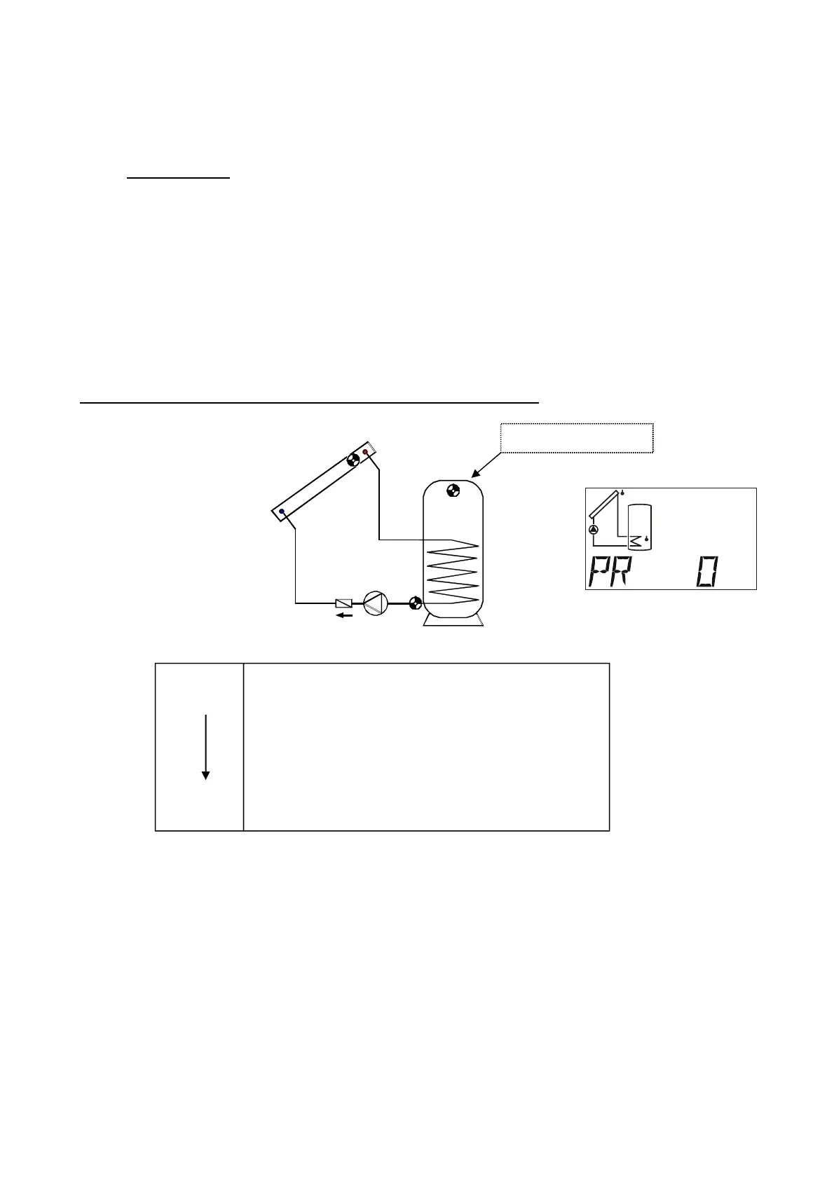
Program 0 - Single solar power system = factory settings
Program 0: Pump A1 runs when:
S1 is greater than the threshold min1 and S1 is greater than S2 by the difference diff1
and S2 has not exceeded the threshold max1.
A1 = S1 > (S2 + diff1) & S1 > min1 & S2 < max1
All programs +1:
In addition, if S3 exceeds the threshold max2, pump A1 is switched off.
S1
S2
A1
S3
S1
min1
S2
max1
diff1
A1
Required settings:
max1 … limit TK S2 A1
max2 … see all programs +1
min1 … switch-on temp.coll. S1 A1
diff1 … coll. S1 – TK S2 A1
S3 for program +1
 Loading...