10
Call: 1-631-648-7481 or Visit: support.technocnc.com
HD Series Manual
NK105G2
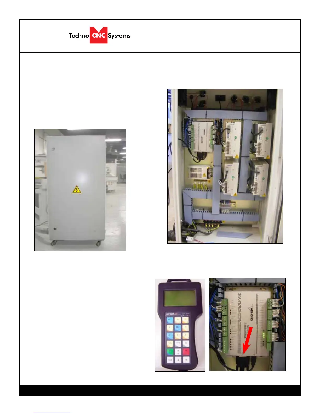
1.3
Take the black connector coming from the Hand-
heldcontroller(g1.3a,)andguideitthrough
the hole in the side of the box.
Locatethecontrollerboard(g1.3b)andattach
the block connector as shown by the red arrow.
Fig. 1.3a Fig. 1.3b
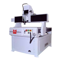
I.2
Open the back of the controller box (shown in Fig 1.2a) with the key provided. The
electronicswillnowbeexposedandcomponentsidentiedinFig1.2b.
Fig. 1.2a
Fig. 1.2b
A
B
A- Controller Board.
B- 24Volt PSU.
C- Stepper Driver.
D- 220Volt In.
D
C
 Loading...