15
codice 09MAXX001
versione EN
revisione 01
Use and Maintenance Manual
MaxX
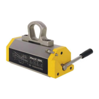
d) Insert the tool into the special hole and turn the
central hub until the threaded hole in which the
lever is to be screwed.
Fig.7.1D
e) While keeping the hub in the position required in
phase d), tighten the lever in its threaded seat and
fasten it completely (Fig. 7.1E2 The lever tightening
values are shown).
Fig.7.1E1
Fig.7.1E2
Torque values for clamping the lever
MaxX 125/250/300E = 25 Nm
MaxX 500/600E = 48 Nm
MaxX 1000 = 85 Nm
MaxX 1500/2000 = 210 Nm
MaxX TG 150 = 25 Nm
MaxX TG 300 = 48 Nm
f) Insert the grub screw into the housing and tighten
it with the tool until the end of stroke to ensure
the locking of the Lever
Fig.7.1F
g) Handle MaxX with the same procedure described
in phase a)
Fig.7.1G
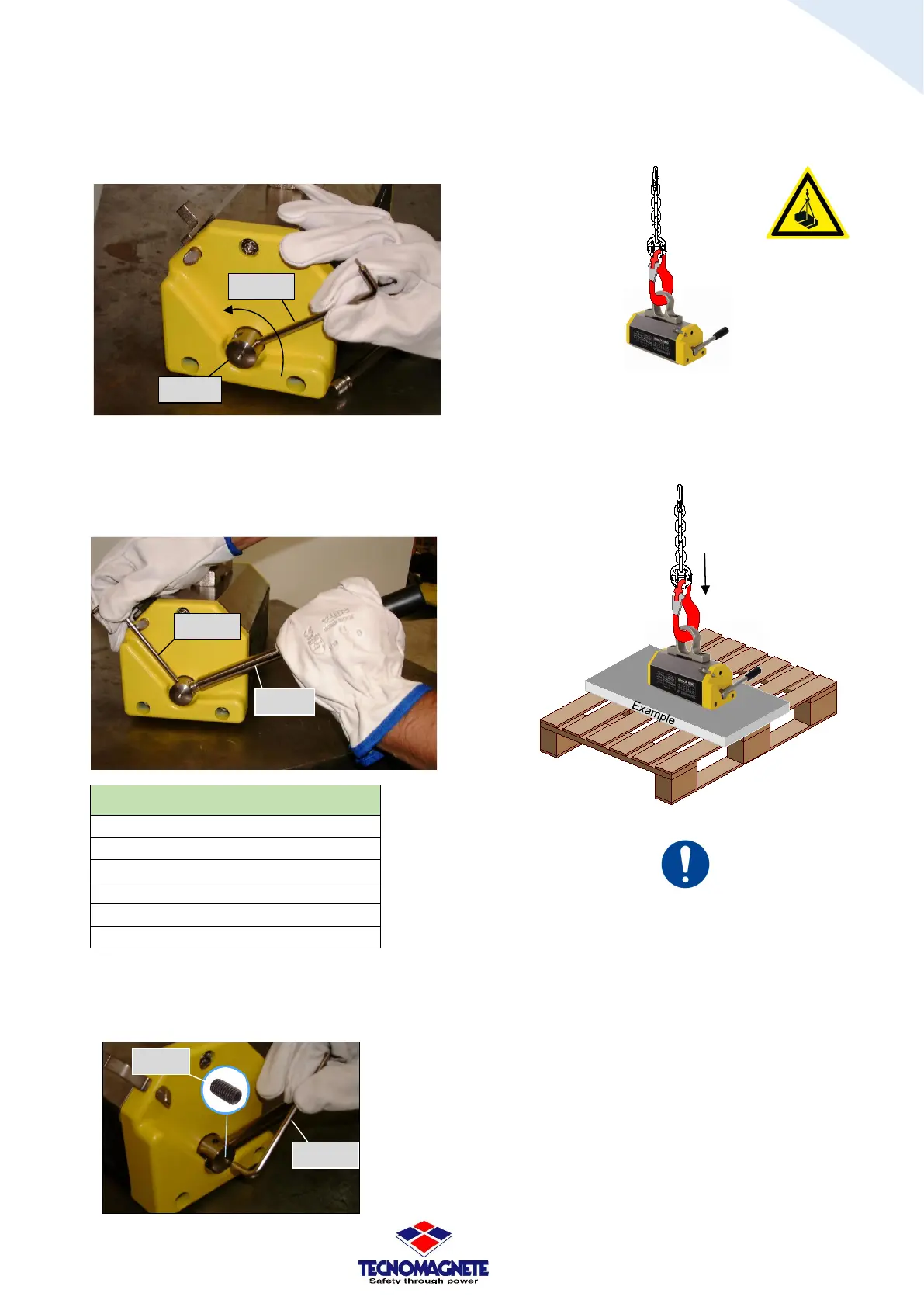
h) Place MaxX on the load to be handled and follow
the procedure described in chapter 9 as regards
the normal use of the equipment.
Fig.7.1H
MaxX is designed to be lifted and handled with suitable
lifting means (as described in paragraph 2.2), the type and
scope of which must be chosen in relation to the weights
of both the MaxX (see paragraph 5.2 table Fig. 5.2B) and
the addition of the load. It is important to periodically
check the structure of the MaxX with particular attention
to the eyebolt
/
load ring(see paragraph 10.12).