9
codice 09MAXX001
versione EN
revisione 01
Use and Maintenance Manual
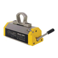
MaxX
N
S
N
S
N
S
N
S
S
S
N
N
4
1
2
5
3
S N
4
1
2
5
3
3.2
Basic principles of magnetic
clamping with MaxX
MaxX is born from TECNOMAGNETE experience in the
development of solutions for the handling of ferrous loads.
The MaxX described in this manual is a hand controlled magnetic
lifter able to move (lift, translate and deposit) ferromagnetic
material
(ex. Steel sheets, plates, rounds, common ferrous material).
MaxX is equipped with a ring-locking bracket and therefore can
only be used as a lifter when hung on a hook of the lifting and
translation means.
MaxX exploits the properties of permanent magnets to create a
magnetic field able to penetrate ferrous materials.
The activation is carried out by means of a lever which rotates a
core in which the permanent magnets are incorporated, so as to
obtain a magnetic flux which in the working phase passes
through the load to be manipulated and in the release phase is
short-circuited inside the lift itself.
The patented magnetic circuit of MaxX lifts conveys the flow
exclusively in the polar area, ie only where it is needed, without
dispersions and without affecting other adjacent loads.
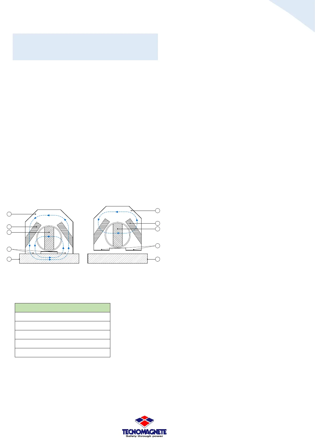
Fig.3.2A Fig.3.2B
Fig.3.2A Magnetization phase (MAG)
Fig.3.2B Demagnetization phase (DEMAG)
Fig.3.2C
Description
Static magneto-permanent core
①
Magneto-permanent nucleus invertible
②
③
④
⑤
The operating cycles of the MaxX are therefore:
- Fig.3.2A in MAG phase the invertible nucleus② is in
parallel to the static one ①. This generates a magnetic
field which, through the poles ③, is completed through
the piece to be anchored⑤.
- Fig.3.2B in the DEMAG phase, the two cores ① and
② are placed in series (rotation of 180 ° of the
invertible core②), constituting a magnetic field which
is short-circuited inside the frame.
Even if the magnetic field acts the same through non-
magnetic bodies (air-dust, non-ferrous materials in
general), maximum efficiency is obtained when the
poles of the same are in good contact with the surface
of the load.
The force curves (see paragraph 3.3), highlight the "fall"
of the anchorage force F (daN) of the lifter with the
increase of the air gap T (in mm), generated by any
"improper presences" between the aforementioned
poles and the load (calamine, foreign bodies,
depressions, protuberances, straps, etc.).
Therefore:
WE RECOMMEND NOT to place MaxX in very dirty or
highly deformed areas of the load. If this is not possible,
follow the performance indications given by the force-
air gap curve according to the characteristics of the load
to be lifted.
WE RECOMMENDED to clean the surfaces of the load
and the poles before placing the lift. If this is not
possible, follow the performance indications given by
the force-air gap curve according to the characteristics
of the load to be lifted.
WE RECOMMENDED, to periodically check the
mechanical condition of the poles ③ to ascertain the
good condition of flatness and the non-damage due to
possible mechanical accidents.