Use and Maintenance Manual
MaxX
9
MAXX
The following is the basic operating procedure for
using the MaxX
9.1
Operating procedure
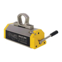
Magnetizing and handling
Before using MaxX
, check that the poles and the contact
surface of the load to be lifted (Fig.9.1.1
) are clean so that
there is no residue of heavy dust and/or chips.
Also clean and check the correct function
stop lever (Fig.9.1.2
) in order to guarantee its functioning
in optimal conditions (check of the spring return).
Fig.9.1.1
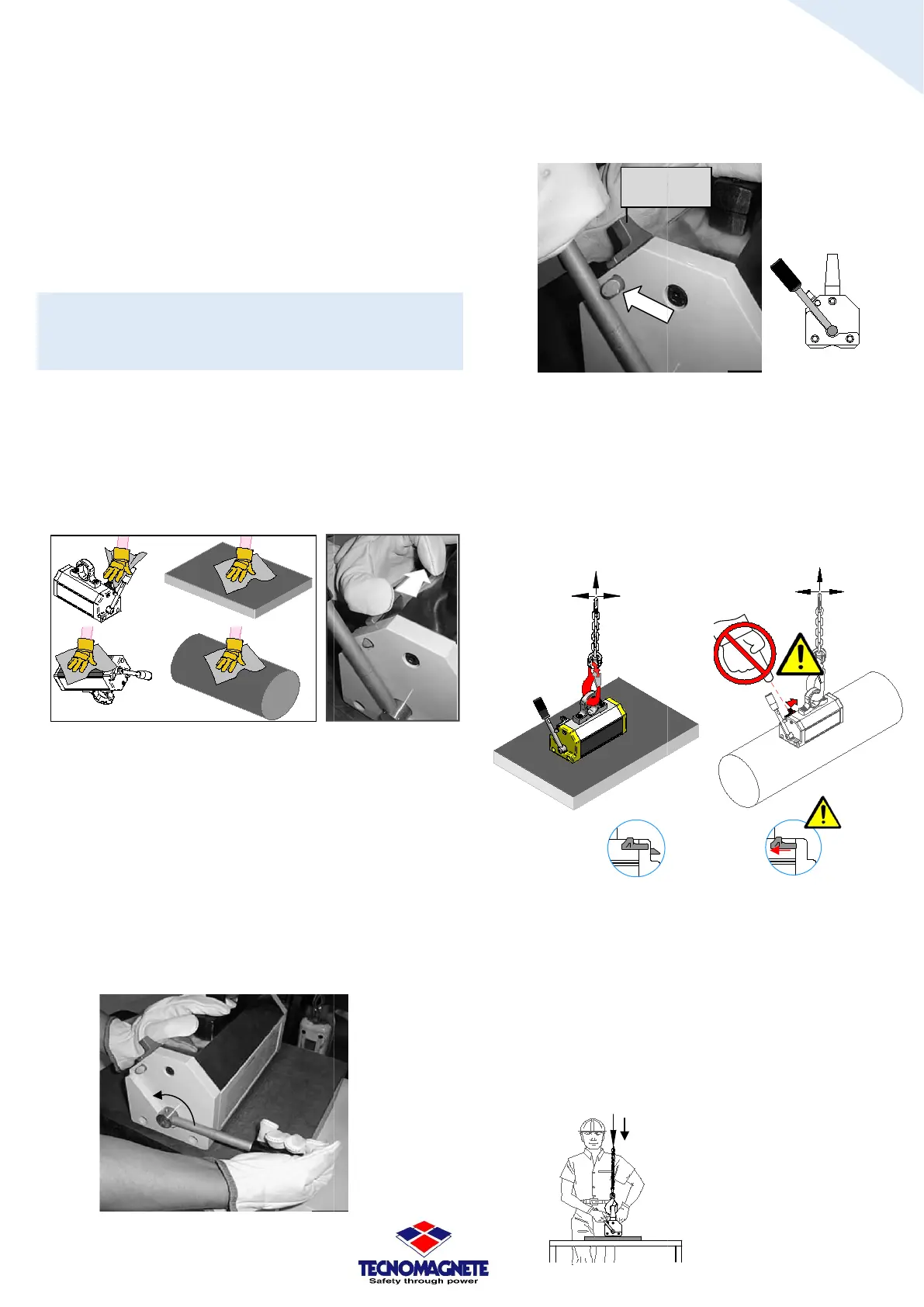
Position MaxX
on the load to be handled paying attention
to its characteristics, with attention to the thickness, as
indicated in paragraph 5.1.
The poles of the MaxX
must be in perfect and total contact
with the load to be handled.
Make sure that the poles of the
centered on the load with g
anchoring of a round or a pipe.
Now proceed with the following steps:
a) Activate MaxX
by turning the lever to the MAG
position.
Fig.9.1A
PROPER USE OF
The following is the basic operating procedure for
Operating procedure
-
, check that the poles and the contact
) are clean so that
there is no residue of heavy dust and/or chips.
Also clean and check the correct function
ing of the pin-
) in order to guarantee its functioning
in optimal conditions (check of the spring return).
1.2
on the load to be handled paying attention
to its characteristics, with attention to the thickness, as
must be in perfect and total contact
MaxX
are perfectly
reater attention to the
by turning the lever to the MAG
b)
Turn the lever until it locks into the mechanical
lever lock.
Fig.9.1B
c)
Pay attention to the weight of the
(see paragraph 5.2 in the table Fig.5.2B) plus the
addition of the weight of the load, after which lift,
by means of a suitable lifting device, and move by
hooking MaxX
from the eyebolt/
the conditions suggested in paragraphs 2.2 a
5.1).
Fig.9.1C1
CAUTION: DO NOT ACIDENTALLY MOVE THE STOP
WITH THE SUSPENSION LOAD, especially for loads with a
high air gap (e.g.: rounds, tubes) because it could cause
the load to come
off and fall accidentally (with the load
anchored NOT in optimal conditions if you move the lever
stop device, bringing it to the OUT service position
Fig.9.1C4
, it could cause the sudden rotation of the lever
from the MAG position to the DEMAG position).
d)
Place the load perfectly on the ground or on a
support suitable for supporting the weights of both
the load and the
Fig.9.1D
Pin lever
(for lever lock)
18
codice 09MAXX001
versione EN
revisione 01
Turn the lever until it locks into the mechanical
Pay attention to the weight of the
MaxX model
(see paragraph 5.2 in the table Fig.5.2B) plus the
addition of the weight of the load, after which lift,
by means of a suitable lifting device, and move by
from the eyebolt/
load ring (observe
the conditions suggested in paragraphs 2.2 a
nd
Fig.9.1C2
CAUTION: DO NOT ACIDENTALLY MOVE THE STOP
-LEVE
WITH THE SUSPENSION LOAD, especially for loads with a
high air gap (e.g.: rounds, tubes) because it could cause
off and fall accidentally (with the load
anchored NOT in optimal conditions if you move the lever
stop device, bringing it to the OUT service position
, it could cause the sudden rotation of the lever
from the MAG position to the DEMAG position).
Place the load perfectly on the ground or on a
support suitable for supporting the weights of both
MaxX
.
IN
service
OUT
service