13
External wiring should be carried out in accordance with following requirement. Check and reassure the
wiring is correct after the wiring is complete.
(Do not utilize the control circuitry buzzer to check the wiring.)
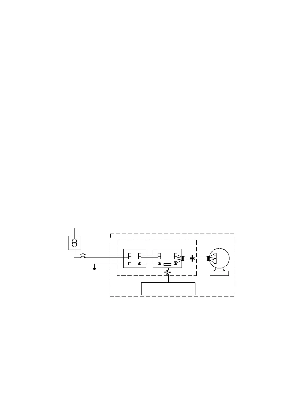
EMI connections:
It is very important that the connections between the inverter, the shielded motor cable, and the EMI
filters are tested as follows.
z Use a metal grounding plate and place the frequency inverter and the EMI filter on the plate.
z Use a shielded motor cable with 4 connectors (U, V, W, & Earth), don’t use the shielding as safety
earth (shield is high frequency earth)
z Remove any paint around the two metal coupling nut holes. So that the metal coupling nuts (and
the shielding) make contact with the frequency inverter and the motor.
z Don't solder a conductor to the shielding.
z Use a metal clamp to connect the shielding from the motor cable with the metal grounding plate.
Now there is a perfect high frequency earth connection between frequency inverter, grounding
plate and EMI filter.
z Keep the distance between the frequency inverter and EMI filter as short as possible (< 30cm) if
longer use a shielded cable with a metal coupling nut and a metal clamp to connect the shielded
cable to the frequency inverter and metal grounding plate.
z The only earth connection between the LISN and the test plate should be via the EMI filter.
z Use a motor which equals the power rating or below of the inverter rating.
z Install a noise filter for inverter onto the output side of the primary circuitry can suppress
conducting noise.
Remote control switches,
relay or similar equipm ents
Power Supply
Power Drive System(PDS)
Metal plate or panel
EMI FILTER
Power Port
Main Transform er
3ΦIM
M
L
NN
LL1
L2
TM2
T1
T2
T3
U
V
W
G
MC C B
Drive
Class B: