27
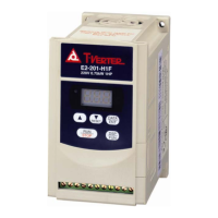
E2-202/203/401/402/403—N4X(IP65)TYPE INSTALLATION:
T1 T2 T3
3 Phases
IM
220-240V
380-480V
Single/ThreePhases
DATA
FUN
DSP
ENT
RUN
RESET
STOP
REV-0-FWD
SWITCH
Potentiometer
POWER
SWITCH
L1(L) L2(N) L3
210.0mm
274.5mm
2.Power supply cable : 4. Torque value of Screw :
E2-200 #12AWG(3.5mm²) (1).Power/Motor cable(TM1,
E2-400 #16AWG(1.25mm²) TM3)
3. Motor cable : Terminal : 8 kgf-cm(6.94 in-lb)
E2-200 #14AWG(2.0mm²) (2).Remote control wire :
E2-400 #16AWG(1.25mm²) 4 kgf-cm(3.47 in-lb)
(3).Outer Cover (M4) :
8kgf-cm(6.94 in-lb)
NOTE:
1.POWER SWITCH,REV-0-FWD SWITCH
AND Potentiometer are only for
E2-202~403-N4S TYPE
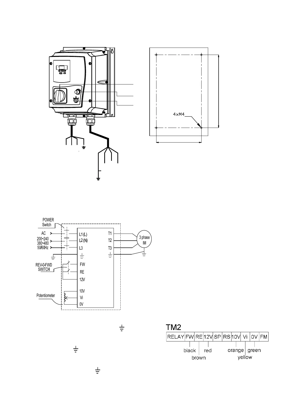
CIRCUIT DIAGRAM
NOTE:
(1).Input source:single-phase(L1(L),L2(N),
) ensuring
that it is connected to a 200/240 supply or three-plase
(L1 (L), L2 (N), L3,
)ensuring that it is connected
to a 200/240,380/480V supply.
(2).Output Motor: three-phase (
, T1, T2, T3).
Caution:
.Do not start or stop the inverter using the main
circuit power.
.FOR E2-202~403--N4S TYPE:
Please always remain REV-0-FWD switch at 0
position. In order to keep inverter has no
running signal before power-on again after
power supply interrupted.Otherwise, injury may
result.
.FOR E2-202~403--N4 TYPE:
Please always remain RE or FW switch at OFF
position. In order to keep inverter has no
running signal before power-on again after
power supply interrupted.Otherwise, injury may
result.