57
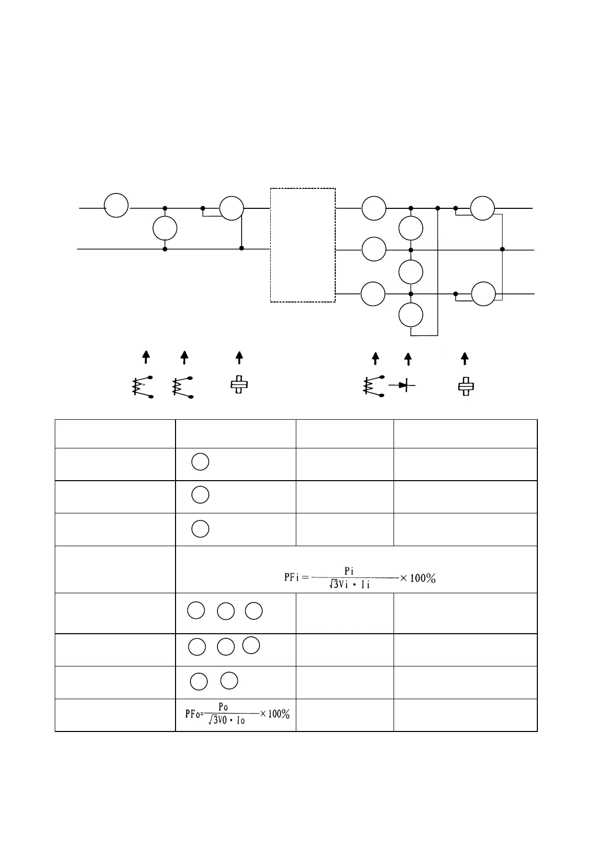
Voltage Current Measurement
The voltage and current measurement on the primary and secondary side of the inverter may be
different due to instrumentation variations. Refer to following diagram for measurement:
Measurement Measuring point Instrument
NOTE
(Measurement criterion)
Input voltage
VI
Moving-iron
Input current
Ii
Moving-iron
Input power
Pi
Power-meter P=W1
Input power factor
PFi
Calculate power factor by the input voltage, input current and input power
Output voltage
Vo
Rectifier
(Moving-iron not
allowed)
Maximum voltage difference
between wires under 3%
Output Current
Io
Moving-iron Under the inverter rated
current
Output power
Po
Power-meter Po=W3+W4
Output power factor
A1
V1
W1 A4
A5
A6
V4
V5
V6
W3
W4
L1
(R)
L2
(S)
T1
(U)
T2
(V)
T3
(W)
Signal-phase
power supply
To motor
Different kinds of
instrument
1
W1
A1
4
5
6
A6
A4
A5
W4
W3