Challenger Series Installation and Quick Programming Manual 13
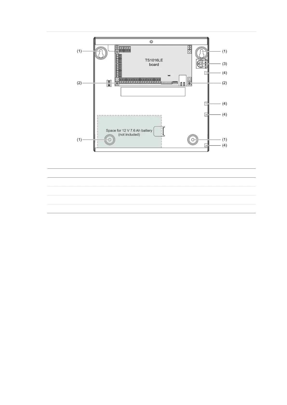
Figure 6: Challenger panel board mounted in enclosure (model TS1016LE)
Figure 6 legend
Description
Enclosure mounting points
Board mounting points (two screws at bottom, slots at top)
. Location of tamper switch
. Accessory board mounting bosses (on side of enclosure)
Installation guidelines
Challenger panels are designed, assembled and tested to meet the requirements
related to safety, emission and immunity with respect to environmental electrical
and electromagnetic interference, as of current relevant standards.
In addition to the general installation guidelines, installers must adhere to any
country dependent requirements of local applicable standards. Only a qualified
electrician or other suitably trained and qualified person should wire to and
provide General Purpose Outlets (GPO) or attempt to wire to the Public Switched
Telephone Network (PSTN).
The general installation guidelines are as follows:
• Mount the unit using screws or bolts through the four mounting holes in the
base. Ensure that the unit is mounted on a flat, solid, vertical surface so that
the base will not flex or warp when the mounting screws or bolts are
tightened.
• Allow 50 mm clearance between the equipment enclosures mounted side by
side, and 25 mm between the enclosure and any side wall or ceiling.
• Models TS1016, TS1016SE, or TS1016LE Challenger panels are powered
and earthed via a 16 Volt AC plug pack.