Challenger Series Installation and Quick Programming Manual 15
3. Slide the board’s terminal connectors together and mount them to the board.
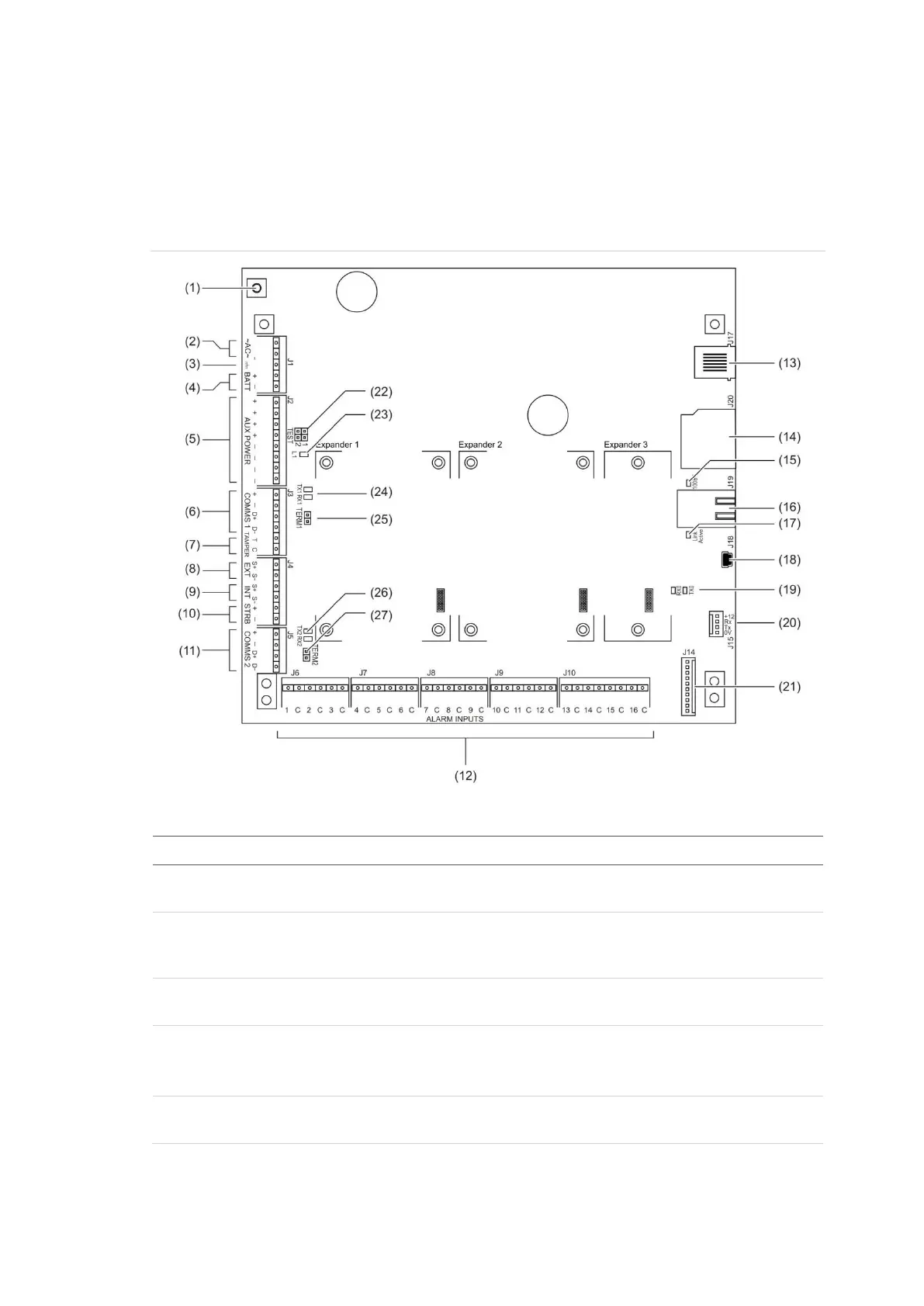
Board details (TS1016, TS1016T, TS1016SE)
See Figure 7 below for models TS1016, TS1016T, or TS1016SE.
Figure 7: Model TS1016, TS1016T, or TS1016SE board details
Figure 7 legend
Description
. Connect one end of each LAN cable shield to the ring terminal and fasten with M3 screw
to the Challenger panel board’s LAN earth terminal.
. Connect the power terminals to a 16 Volt AC plug pack (TS1016 or TS1016SE) or to the
mains transformer (TS1016T), as applicable. Maximum current drawn by the panel with
no peripheral devices connected is approximately 200 mA.
. Connect the power earth terminal to the plug pack earth wire (TS1016 or TS1016SE) or
to the mains earth wire (TS1016T), as applicable.
. Connect the + and – terminals to a 12 V sealed lead acid battery (7.6 Ah recommended),
not supplied.
Note: A battery must be connected in order to use internal or external siren speakers.
. Connect the + and – auxiliary power output terminals to devices that require 12 Volt DC
power, such as detectors. See “Auxiliary power terminals” on page 21.


 To Next Page