18 Challenger Series Installation and Quick Programming Manual
Board details (TS1016LE)
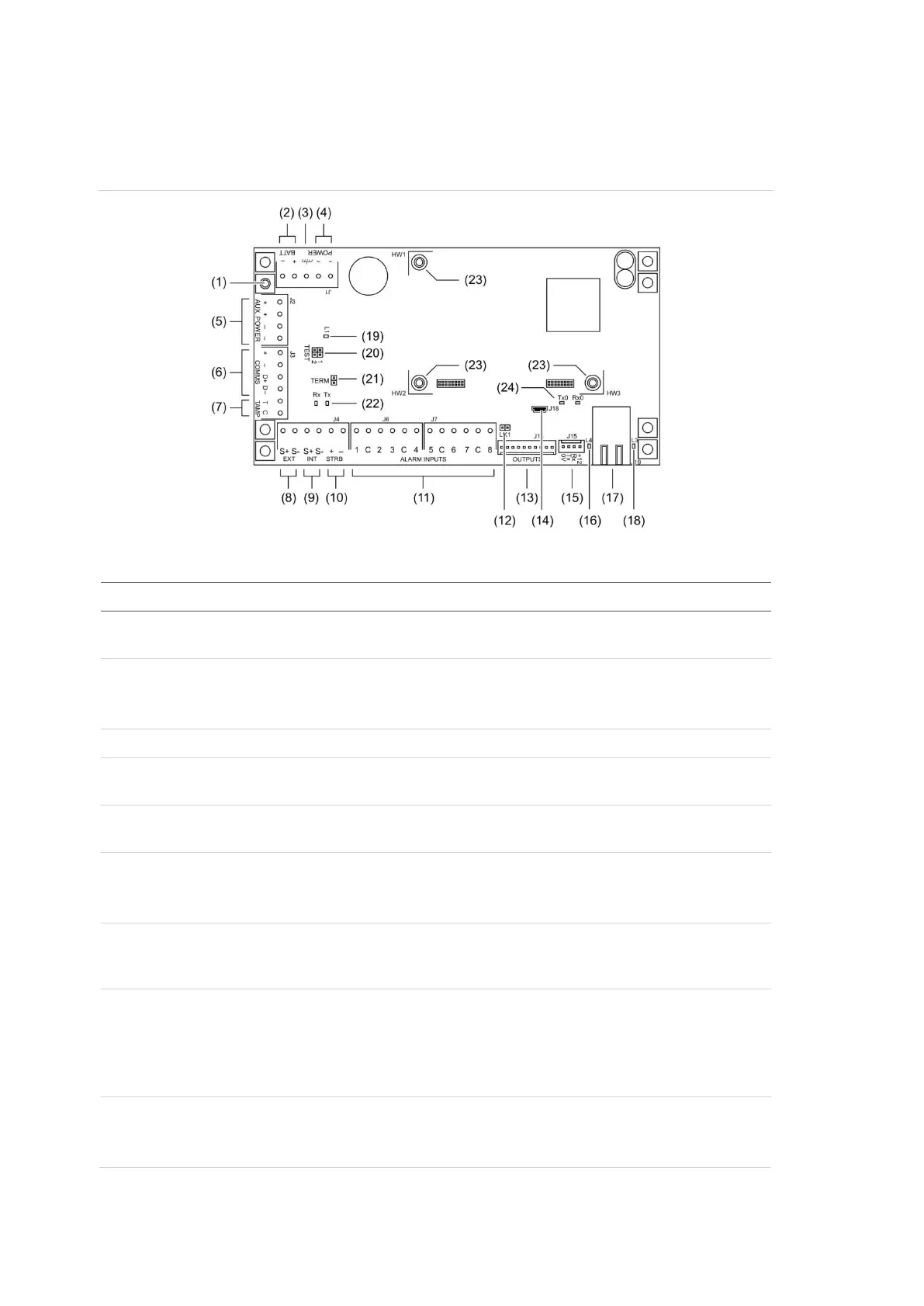
See Figure 9 below for model TS1016LE.
Figure 9: Model TS1016LE board details
Figure 9 legend
Description
.
Connect one end of the LAN cable shield to the ring terminal and fasten with M3 screw to
the Challenger panel board’s LAN earth terminal.
. Connect the + and – terminals to a 12 V sealed lead acid battery (7.6 Ah recommended),
not supplied.
Note: A battery must be connected in order to use internal or external siren speakers.
. Connect the power earth terminal to the plug pack earth wire.
. Connect the power terminals to a 16 Volt AC plug pack. Maximum current drawn by the
panel with no peripheral devices connected is approximately 100 mA.
. Connect the + and – auxiliary power output terminals to devices that require 12 Volt DC
power, such as detectors. See “Auxiliary power terminals” on page 21.
. Connect the D+ and D– terminals to the RS-485 data cable.
If the + and –
terminals are used, consider the current draw as part of the auxiliary power
output. See “Auxiliary power terminals” on page 21.
. Input and common terminals for panel tamper switch (supplied). Short circuit for sealed,
open circuit for unsealed. Must be sealed if not used. Can only be used with normally
closed contacts such as the panel tamper switches.
. Connect the S+ and S– terminals to an external 8 Ω siren speaker. If an external siren is
not used, connect the S+ and S– terminals to a 1K 1/4 watt resistor (supplied). The
maximum current draw for the external 8 Ω siren and the strobe is 700 mA.
The internal and external siren speaker outputs are relay 16 and are mapped to event
flag 1.
. Connect the S+ and S– terminals to an internal 8 Ω siren speaker.
If an internal siren is used, consider the current draw as part of the auxiliary power output.
See “Auxiliary power terminals” on page 21.