iii
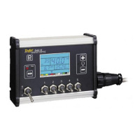
844E Sprayer Crontrol
98-70006 R3
Table of Contents
INTRODUCTION 2
MOUNTING SPRAYER COMPONENTS 3
Pressure Regulator in Bypass Mode ...................................................................................... 3
Pressure Regulator in Throttling Mode ................................................................................ 5
Flow Meter .............................................................................................................................. 6
Boom Control Valves .............................................................................................................. 6
Pressure Transducer ............................................................................................................... 6
INSTALLING THE SPEED SENSOR ASSEMBLY 7
Components .................................................................................................................................................7
Speed Step 1 - Location .......................................................................................................... 7
Proximity Sensor (optional) ........................................................................................................................7
Speed Step 2 - Installing The Wheel Magnets ...................................................................... 8
Speed Step 3 - Installing the Magnetic Sensor ..................................................................... 9
Speed Step 4 - Con rming Speed Sensor Installation ....................................................... 10
Magnetic Wheel Sensor ............................................................................................................................10
Radar ..........................................................................................................................................................10
MOUNTING THE TEEJET 844 CONSOLE 11
Console Step 1 - Location ..................................................................................................... 11
Console Step 2 - Mounting ................................................................................................... 11
Console Step 3 - Power Connection .................................................................................... 12
Console Step 4 - Connecting Component Cables ............................................................... 14
Connect Step 1 - Wiring Layout ........................................................................................... 15
Connect Step 2 - Making The Connection ........................................................................... 16