16
www.teejet.com
844E Sprayer Control
Connect Step 2 - Making The Connection
Now, extend the cable leads to the Flow meter or Pressure Sensor, and Wheel Sensor or Radar Sensor to the
furthest component. Select the appropriate lead and connect to this component. Run the cable to the other
component, taking care to safely secure the cable along the route. Refer to the diagram on page 10.
Repeat this procedure with the cable leads to the Pressure Regulating Valve and the Boom Control Valves. Refer
to the chart below when attaching the boom section wires. T-tap connectors must be attached to the +12vDc
and ground wires to connect them to the boom control valves (when using ball valves), which should be evenly
distributed across the two.
If both the fl ow meter and pressure transducer are not used simultaneously, there will be one extra connection on
the cable. Simply tie this part of the cable back as it will not be used.
When all connections have been made, connect the large plug into the side of the Control Console.
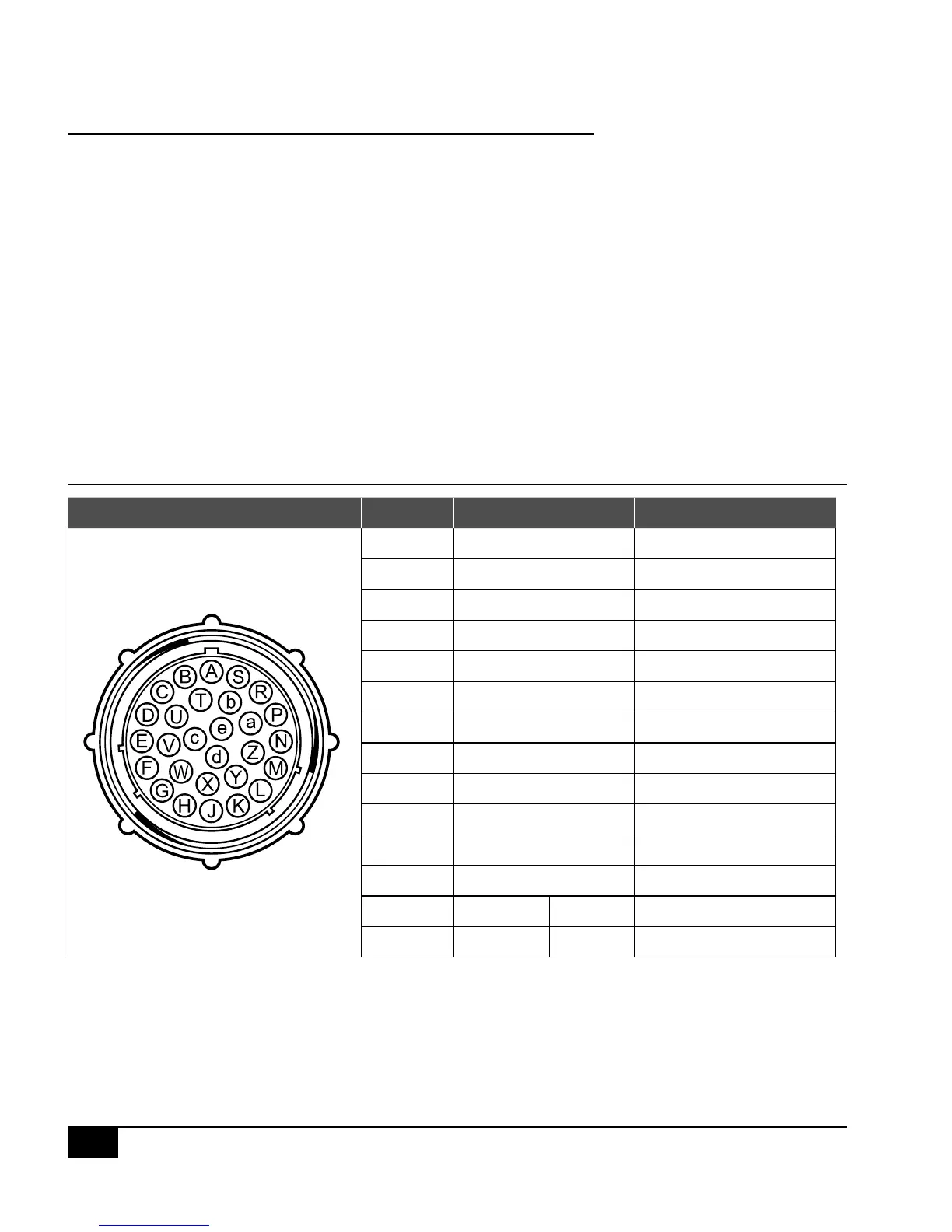
Figure 1-15: Console Connector
Console Connector Pin No. Wire Color Signal Name
B White Section 1
C Brown Section 2
D Green Section 3
E Yellow Section 4
F Gray Section 5
R White Flow Signal
S White Pressure Signal
T White Speed Signal
V Brown Power Out
a White Regulation Valve (+)
b Brown Regulation Valve (+)
c Blue +12 VDC
d Blue Pink Ground Free End (Valves)
e Red Black +12 VDC Free End