3.2.2 Resistance measurement
To avoid electrical shock and/or damage to the
instrument, disconnect circuit power and
discharge all high-voltage capacitors before
measuring resistance.
The Meter's resistance ranges are 600.0, 6.000k,
60.00k, 600.0k, 6.000M and 60.00M.
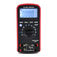
To measure resistance (set up the Meter as shown in figure
3-2):
1. Set the rotary switch to range.
2. Connect the black and red test leads to the COM and V
terminals respectively.
3. Connect the test leads to the circuit being measured and
read the displayed value.
Some tips for measuring resistance:
The measured value of a resistor in a circuit is often
different from the resistor's rated value. This is because the
Meter's test current flows through all possible paths
between the probe tips.
In order to ensure the best accuracy in measurement of low
resistance, short the test leads before measurement and
memory the test probe resistance in mind. This necessary to
subtract for the resistance of the test leads.
The resistance function can produce enough voltage to
forward-bias silicon diode or transistor junctions, causing
them to conduct. To avoid this, do not use the 60M range
for in-circuit resistance measurements.