EasyManua.ls Logo

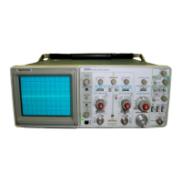
Tektronix 2235 - INSTRUMENT COOLING; CONTROLS, CONNECTORS, AND INDICATORS; POWER, DISPLAY, AND PROBE ADJUST

Tektronix 2235
229 pages
To Next Page IconTo Next Page
To Previous Page IconTo Previous Page
Loading...
O
p
e
rati
ng
I
n
str
u
ctions-2235
Service
CA
U
TIO
N
FOR
C
σΝΤιΝυεσ
FIRE
PRCTECTION
R
EPL
AC
E
ONL
Y
WIT
H
SPE
CI
F I
E D
TYPEAN
Ο
RATED
FUS
E
.
σ
1SCO
NNE
CT
POW
E
R
INPUT
BEF
OR
E
ΑΣΡιΑςιΝ
G
FU
S E
L
IN
E
VO L
T
A
G
E R
AN
GE
FUSE 250V
9015
ΟΥΑ
[
ΙΑ
SLOW
DO
NOT
REM
O V
E
COV
E
R
.
R EFER
5
E
R
V
I[I
N G TO
COAL
I
F
I
ED
ΡΕΟ
S
ΟΝΝ
FL
.
POWER
ΜΑ
% WA
TTS
4
σ
ΜΑΧ
VA
70
F
F
Ι
1
45
-
440
Η
;
POWER
CORD
L
I
NE
FU
S
E
CAUTION
TO
AVOID
ELECTRIC
SHOCK
THE
POWER
CORO
PROTECTIVE
GROUNDING
CONDUC70
π
4111T
BE
CONNECTED
ι
t
ρυΝυ
.
ιαι L
AXIS
INPUT
ισχα Ρσ
s
ιτινε
GOING
ΙΝΡυΤ
O F
CAE
Α
S ES
'-'-
INTENSITY
5
VOLT
Ρ
-
Ρ
CAUSES
' 1
N
OTIC
E
A
BLE
:
ΜΟσ
U
ΙΑΤΙΟΝ
ΑΤ
~ N OR
M
A
L
ΙΝΤΕΝ
5
ΓΤΥ
.
°
-310V
PEAK
4207-03
Figure
2-2
.
Fuse
hol
de
r
and
power co
rd
con
n
ecto
r .
5
.
R
einstall t
h
e
fuse
(o
r r
ep
lacement
fuse)
and
t
h
e
fuse-
h
olde
r
cap
.
I
N
ST
RUMEN
T
COO
L
I
N
G
Always
maintain
a
d
eq
u
ate
instr
u
ment
cooling
.
T
he ve
n
ti-
lation
holes
on
bot
h
side
of
t
h
e eq
ui
pm
e
n
t
cabinet
and
on
t
h
e
r
ea
r
p
a
n
el
must
remai
n
f
r
ee
of
o
b
structions
.
CO
N
T
R
O
L
S,
CO
NNE
CTO
R
S,
A
N
D
I
N
DICATO
R
S
The
following
d
escri
p
tions
are
inten
d
ed
to
familiarize
t
he
4
Ο
FOCUS
Co
n
tr
ol-A
d
justs
far
optimum
d
isplay
op
erator
wit
h
t
h
e
location,
operation,
and
fu
n
ction
of
t
he
d
efi
n
itio
n
.
instr
ument's
controls,
connectors,
a
n
d
i
n
dicato
r
s
.
P
O
WER,
DIS
PL
AY,
A
ND
PR
O
BE
AD
JU
ST
Refer
to
Figu
r
e
2-3
fo
r
locatio
n
of
items
1
t
h
ro
u
g
h
8
.
Internal
Graticule-Eliminates
p
arallax
viewing
error
betwee
n
t
he
trace
an
d
gratic
u
le
lines
.
R
ise-time
am
p
li-
t
ude and
meas
u
re
m
ent
points
are
indicated
at
t
he
left
edge
of
t
he g
r
atic
u
le
.
POWER
Switch--Turns
instr
u
ment
power
on
and
off
.
Press
in
for
ON
;
press again
for
O
FF
.
Ο
Power
Indicator-An
LE
D
t
h
at
illuminates
w
hen
pow-
er
is
availa
b
le
to
t
he
instrument
a
nd
t
he
PO
W
ER
switc
h
is
set
to
ON
(
bu
tton
in)
.
2-2
PR
O
BE
AD
JU
ST
Con
n
ector-
P
rov
id
es an
approxi-
mately
0
.5
V,
negative-going,
square-wave
voltage
(at
a
p
proximately
1
kH
z)
that
pe
rm
its
an
o
pe
r
ato
r
to
compensate
voltage
pr
obes
an
d
t
he check
operation
o
f
t
he
oscilloscope
vertical
system
.
It is
not
i
n
tended
to
ve
r
ify
t
he acc
u
racy of
t
h
e
vertical
gain
o
r
ti
m
e-base
circ
u
itry
.
BEAM
F
I
N
D
Switch
-
Wh
en h
eld
in,
co
mpr
esses
t
h
e
d
isplay
to
wit
h
in
t
he g
r
aticule
a
r
ea
an
d
provi
des α
visi-
b
le
viewing
i
n
te
n
sity
to
ai
d
in
locating
off-scree
n
dis
p
lays
.
TR
AC
E
ROTATION
Control-Screwdriver
a
d
ju
st-
me
n
t
use
d
to
align
t
h
e
crt
trace
wit
h
t
h
e
h
orizo
n
tal
g
r
aticule
lines
.

Table of Contents

Other manuals for Tektronix 2235

Related product manuals