Performance Characteristics
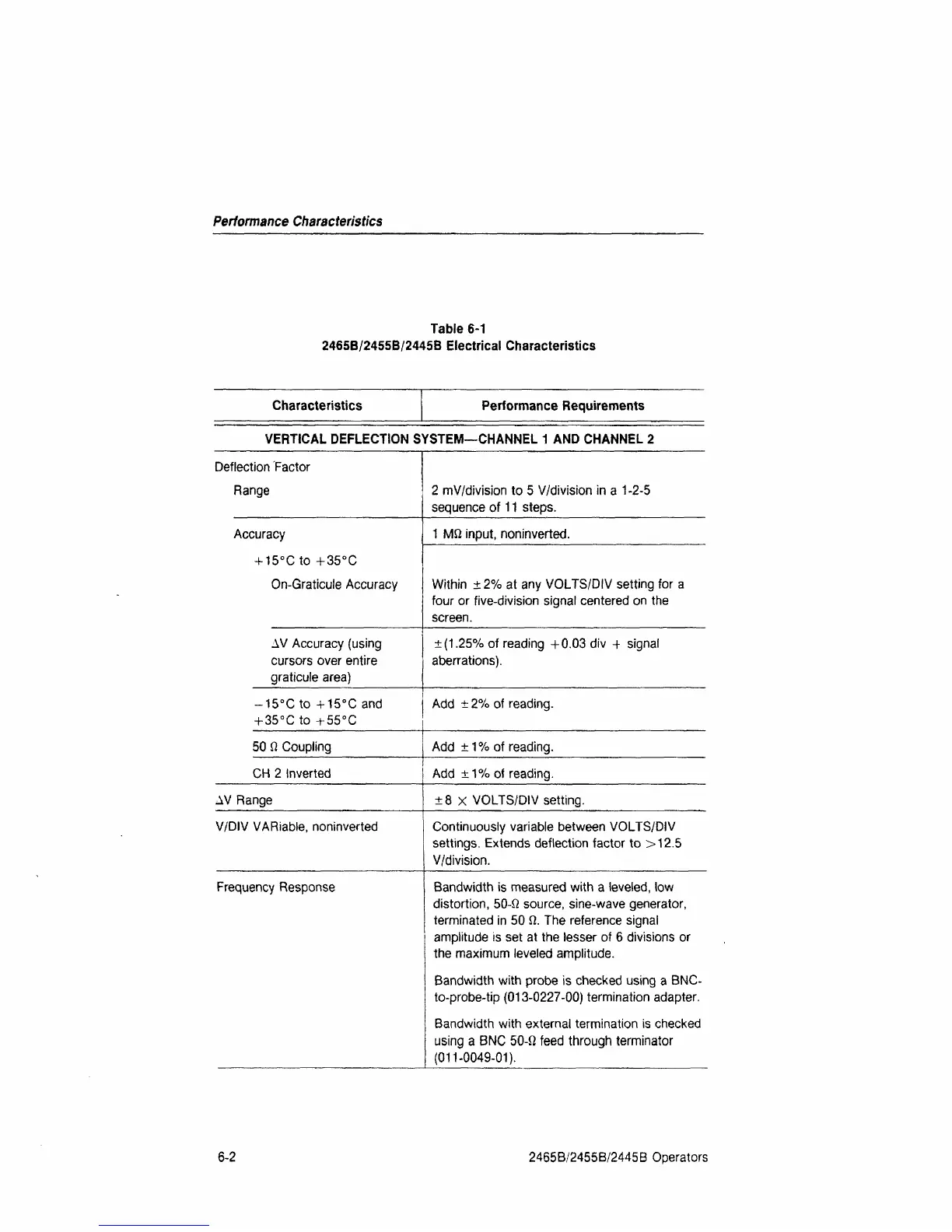
Table 6-1
2465B/2455B/2445B Electrical Characteristics
Characteristics Performance Requirements
VERTICAL DEFLECTION SYSTEM—CHANNEL
1
AND CHANNEL 2
Deflection Factor
Range
Accuracy
+ 15°C to +35°C
On-Graticule Accuracy
AV Accuracy (using
cursors over entire
graticule area)
-15°C to +15°C and
+
35°C
to + 55°C
50
Q
Coupling
2 mV/division to 5 V/division in a
1
-2-5
sequence of
11
steps.
1 MQ input, noninverted.
Within ±
2%
at any VOLTS/DIV setting for a
four or five-division signal centered on the
screen.
±(1.25%
of reading +0.03 div + signal
aberrations).
Add ±
2%
of reading.
Add
±1%
of reading.
CH 2 Inverted Add
±1%
of reading.
AV Range ±8 X VOLTS/DIV setting.
V/DIV VARiable, noninverted Continuously variable between VOLTS/DIV
settings. Extends deflection factor to >12.5
V/division.
Frequency Response Bandwidth is measured with a leveled, low
distortion,
50-Q source, sine-wave generator,
terminated in 50 ft. The reference signal
amplitude is set at the lesser of 6 divisions or
the maximum leveled amplitude.
Bandwidth with probe is checked using a BNC-
to-probe-tip (013-0227-00) termination adapter.
Bandwidth with external termination is checked
using a BNC 50-ft feed through terminator
(011-0049-01).
6-2
2465B/2455B/2445B Operators
 Loading...


