Performance Characteristics
Table 6-1 (cont)
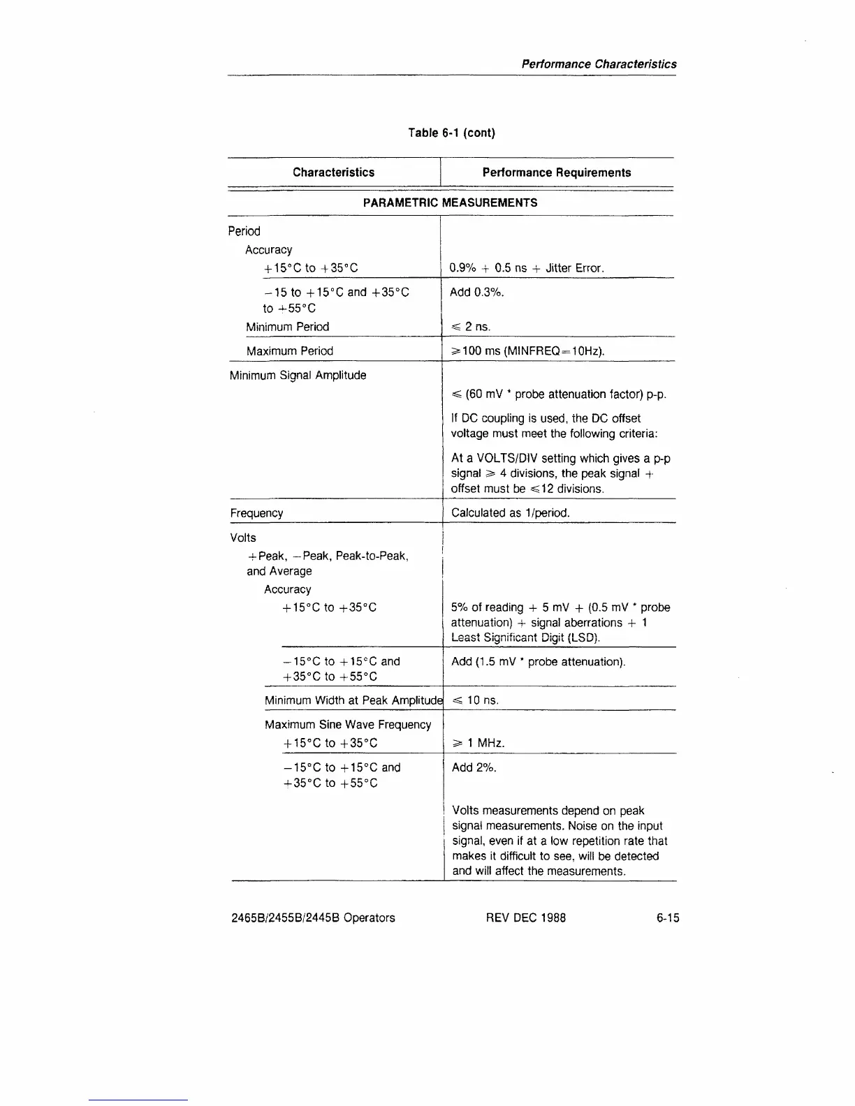
Characteristics
Performance Requirements
PARAMETRIC MEASUREMENTS
Period
Accuracy
+ 15°Cto +35°C
-15 to + 15°Cand +35°C
to -^-55°C
Minimum Period
Maximum Period
Minimum Signal Amplitude
Frequency
Volts
0.9% + 0.5 ns + Jitter Error.
Add 0.3%.
< 2 ns.
2*100 ms
(MINFREQ
=
10Hz).
< (60 mV * probe attenuation factor) p-p.
If DC coupling is used, the DC offset
voltage must meet the following criteria:
At a VOLTS/DIV setting which gives a p-p
signal s* 4 divisions, the peak signal +
offset must be «s12 divisions.
Calculated as 1/period.
-!-Peak, -Peak, Peak-to-Peak,
and Average
Accuracy
+ 15°Cto +35°C
-15°Cto + 15°C and
+
35°C
to + 55°C
5% of reading -+- 5 mV + (0.5 mV * probe
attenuation) -f- signal aberrations + 1
Add (1.5 mV * probe attenuation).
Minimum Width at Peak Amplitude
« 10 ns.
Maximum Sine Wave Frequency
+ 15°Cto +35°C
1 MHz.
-15°C to +15°C and
-35°Cto +55°C
Add 2%.
Volts measurements depend on peak
signal measurements. Noise on the input
signal,
even if at a low repetition rate that
makes it difficult to see, will be detected
and will affect the measurements.
2465B/2455B/2445B Operators
REV DEC 1988
6-15
 Loading...


