Maintenance—2465B/2467B Service
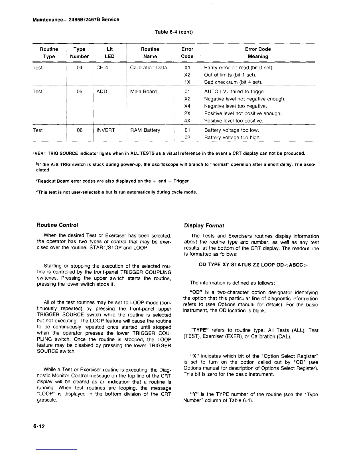
Table 6-4 (cont)
Routine
Type
Test
Test
Test
Type
Number
04
05
06
Lit
LED
CH 4
ADD
INVERT
Routine
Name
Calibration Data
Main Board
RAM Battery
Error
Code
X1
X2
1X
01
X2
X4
2X
4X
01
02
Error Code
Meaning
Parity error on read (bit 0 set).
Out of limits (bit 1 set).
Bad checksum (bit 4 set).
AUTO LVL failed to trigger.
Negative level not negative enough.
Negative level too negative.
Positive level not positive enough.
Positive level too positive.
Battery voltage too low.
Battery voltage too
high.
a
VERT TRIG SOURCE indicator lights when in ALL TESTS as a visual reference in the event a CRT display can not be produced.
b
lf the A/B TRIG switch is stuck during power-up, the oscilloscope will branch to "normal" operation after a short delay. The asso-
ciated
c
Readout Board error codes are also displayed on the + and — Trigger
d
This test is not user-selectable but is run automatically during cycle mode.
Routine Control
When the desired Test or Exerciser has been selected,
the operator has two types of control that may be exer-
cised over the routine: START/STOP and LOOP.
Starting or stopping the execution of the selected
rou-
tine is controlled by the front-panel TRIGGER COUPLING
switches. Pressing the upper switch starts the routine;
pressing the lower switch stops it.
All of the test routines may be set to LOOP mode
(con-
tinuously repeated) by pressing the front-panel upper
TRIGGER SOURCE switch while the routine is selected
but not executing. The LOOP feature will cause the routine
to be continuously repeated once started until stopped
when the operator presses the lower TRIGGER
COU-
PLING switch. Once the routine is stopped, the LOOP
feature may be disabled by pressing the lower TRIGGER
SOURCE switch.
While a Test or Exerciser routine is executing, the Diag-
nostic Monitor Control message on the top line of the CRT
display will be cleared as an indication that a routine is
running.
When test routines are looping, the message
"LOOP"
is displayed in the bottom division of the CRT
graticule.
Display Format
The Tests and Exercisers routines display information
about the routine type and number, as well as any test
results, at the bottom of the CRT display. The readout line
is formatted as follows:
OD TYPE XY STATUS ZZ LOOP OD<ABCC>
The information is defined as follows:
"OD"
is a two-character option designator identifying
the option that this particular line of diagnostic information
refers to (see Options manual for details). For the basic
instrument, the OD location is blank.
"TYPE"
refers to routine type: All Tests (ALL), Test
(TEST), Exerciser (EXER), or Calibration (CAL).
"X" indicates which bit of the "Option Select Register"
is set to turn on the option called out by "OD" (see
Options manual for description of Options Select Register).
This bit is zero for the basic instrument.
"Y" is the TYPE number of the routine (see the "Type
Number" column of Table 6-4).
6-12

 Loading...


