Maintenance—2465B/2467B Service
"STATUS" shows the results of the last time a selected
test routine ran: either PASS or FAIL. This space is blank
for exerciser and calibration routines. When the
diagnostics are called up from normal operating mode, the
space will be blank until the selected test is executed.
"ZZ"
is a two-digit error code identifying the nature of
the failure in a failed test (see the "Error Code" column of
Table 6-4).
"LOOP"
indicates when a selected test is set to the
LOOP mode.
"OD<ABCC>" is the CYCLE mode failure indicator.
CYCLE mode, when entered by removing the NO
CAL/CAL jumper (P501) before turning the instrument on,
causes the instrument to continuously LOOP through the
Power Up Diagnostic Tests. If a failure occurs, the cycle-
failure data, identifying the first failure encountered, is
written to RAM. Thereafter, at each power-up, the
Diagnostic Monitor is automatically entered, and the failure
data is displayed. The failure data must be cleared from
the RAM location to eliminate the CYCLE mode failure
display (see CYCLE ERROR CLEAR Exerciser 03). The
information displayed is an abbreviated version of the
previous items:
"OD"
is a two-character option designator showing
which option failed first while in the CYCLE mode (the
same codes as for "OD" at the start of the readout line).
"A" identifies the option-select bit for the failing option
(the same code as for "X").
"B"
is the test Type Number where the failure occurred
(the same codes as for "Y").
"CC"
is the error code for the test (the same codes as
for "ZZ").
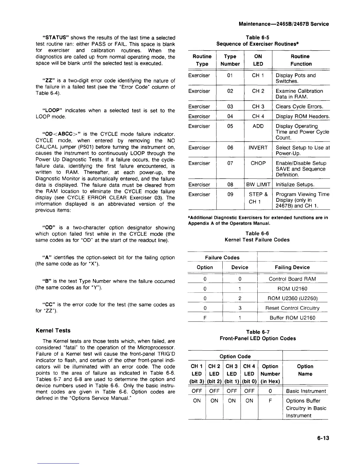
Kernel Tests
The Kernel tests are those tests which, when failed, are
considered
"fatal"
to the operation of the Microprocessor.
Failure of a Kernel test will cause the front-panel TRIG'D
indicator to flash, and certain of the other front-panel
indi-
cators will be illuminated with an error code. The code
points to the area of failure as indicated in Table 6-6.
Tables 6-7 and 6-8 are used to determine the option and
device numbers used in Table 6-6. Only the basic instru-
ment codes are given in Table 6-6. Option codes are
defined in the "Options Service Manual."
Table 6-5
Sequence of Exerciser Routines
8
Routine
Type
Exerciser
Exerciser
Exerciser
Exerciser
Exerciser
Exerciser
Exerciser
Exerciser
Exerciser
Type
Number
01
02
03
04
05
06
07
08
09
ON
LED
CH 1
CH 2
CH 3
CH 4
ADD
INVERT
CHOP
BW LIMIT
STEP &
CH 1
Routine
Function
Display Pots and
Switches.
Examine Calibration
Data in RAM.
Clears Cycle Errors.
Display ROM Headers.
Display Operating
Time and Power Cycle
Count.
Select Setup to Use at
Power-Up.
Enable/Disable Setup
SAVE and Sequence
Definition.
Initialize Setups.
Program Viewing Time
Display (only in
2467B)and CH 1.
"Additional Diagnostic Exercisers for extended functions are in
Appendix A of the Operators Manual.
Table 6-6
Kernel Test Failure Codes
Failure Codes
Option
0
0
0
0
F
Device
0
1
2
3
1
Failing Device
Control Board RAM
ROM U2160
ROM U2360 (U2260)
Reset Control Circuitry
Buffer ROM U2160
Table 6-7
Front-Panel LED Option Codes
Option Code
CH 1
LED
(bit 3)
OFF
ON
CH 2
LED
(bit 2)
OFF
ON
CH3
LED
(bit 1)
OFF
ON
CH4
LED
(bit 0)
OFF
ON
Option
Number
(in Hex)
0
F
Option
Name
Basic Instrument
Options Buffer
Circuitry in Basic
Instrument
ON ON ON ON F Options Buffer
Circuitry in Basic
Instrument
6-13