Maintenance—2465B/2467B Service
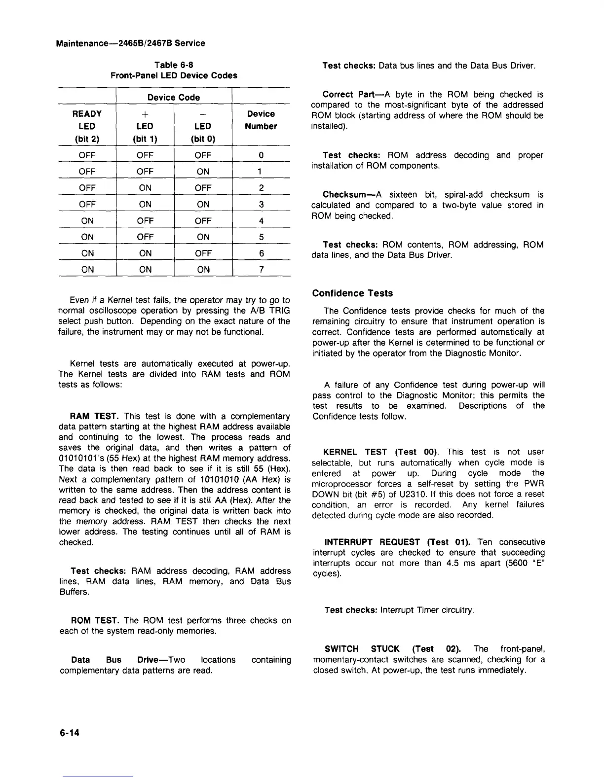
Table 6-8
Front-Panel LED Device Codes
READY
LED
(bit 2)
OFF
OFF
OFF
OFF
ON
ON
ON
ON
Device Code
+
LED
(bit 1)
OFF
OFF
ON
ON
OFF
OFF
ON
ON
LED
(bit 0)
OFF
ON
OFF
ON
OFF
ON
OFF
ON
Device
Number
0
1
2
3
4
5
6
7
Even if a Kernel test fails, the operator may try to go to
normal oscilloscope operation by pressing the A/B TRIG
select push button. Depending on the exact nature of the
failure,
the instrument may or may not be functional.
Kernel tests are automatically executed at power-up.
The Kernel tests are divided into RAM tests and ROM
tests as follows:
RAM TEST. This test is done with a complementary
data pattern starting at the highest RAM address available
and continuing to the lowest. The process reads and
saves the original data, and then writes a pattern of
01010101's (55 Hex) at the highest RAM memory address.
The data is then read back to see if it is still 55 (Hex).
Next a complementary pattern of 10101010 (AA Hex) is
written to the same address. Then the address content is
read back and tested to see if it is still AA (Hex). After the
memory is checked, the original data is written back into
the memory address. RAM TEST then checks the next
lower address. The testing continues until all of RAM is
checked.
Test checks: RAM address decoding, RAM address
lines,
RAM data lines, RAM memory, and Data Bus
Buffers.
ROM TEST. The ROM test performs three checks on
each of the system read-only memories.
Data Bus Drive—Two locations containing
complementary data patterns are
read.
6-14
Test checks: Data bus lines and the Data Bus Driver.
Correct Part—A byte in the ROM being checked is
compared to the most-significant byte of the addressed
ROM block (starting address of where the ROM should be
installed).
Test checks: ROM address decoding and proper
installation of ROM components.
Checksum—A sixteen bit, spiral-add checksum is
calculated and compared to a two-byte value stored in
ROM being checked.
Test checks: ROM contents, ROM addressing, ROM
data lines, and the Data Bus Driver.
Confidence Tests
The Confidence tests provide checks for much of the
remaining circuitry to ensure that instrument operation is
correct. Confidence tests are performed automatically at
power-up after the Kernel is determined to be functional or
initiated by the operator from the Diagnostic Monitor.
A failure of any Confidence test during power-up will
pass control to the Diagnostic Monitor; this permits the
test results to be examined. Descriptions of the
Confidence tests follow.
KERNEL TEST (Test 00). This test is not user
selectable, but runs automatically when cycle mode is
entered at power up. During cycle mode the
microprocessor forces a self-reset by setting the PWR
DOWN bit (bit #5) of U2310. If this does not force a reset
condition,
an error is recorded. Any kernel failures
detected during cycle mode are also recorded.
INTERRUPT REQUEST (Test 01). Ten consecutive
interrupt cycles are checked to ensure that succeeding
interrupts occur not more than 4.5 ms apart (5600 "E"
cycles).
Test checks: Interrupt Timer circuitry.
SWITCH STUCK (Test 02). The front-panel,
momentary-contact switches are scanned, checking for a
closed switch. At power-up, the test runs immediately.